Whether for packaging machinery, life sciences technology, office equipment or factory automation, smooth motion, fast accelerations and a high degree of accuracy are hallmark requirements for linear actuators. Increasingly, miniaturization has added another requirement: compactness.
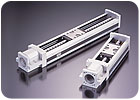
One system that meets all these requirements is the single-axis ballscrew actuator. Ballscrews convert rotary motion to linear motion, and vice versa. A ballscrew actuator consists of a ballscrew and nut, a slide block or carriage, guide rails, and bearing supports for each end of the screw. The stage is mounted to the carriage. To eliminate backlash, the movement of the carriage is guided by recirculating steel balls that roll between it and the raceways of the guide rails.
Traditionally, many equipment manufacturers designed and assembled their own custom ballscrew actuators. In fact, many semiconductor manufacturers and medical equipment manufacturers still do. To design a custom actuator, engineers have to find the right ballscrew, carriage and guide rails. They also need motor brackets and supports for the ballscrew. After mounting all the components, repeated adjustments are usually necessary for optimal operation.
Moreover, a custom ballscrew actuator is usually larger than a comparable off-the-shelf system. That’s because in a preconfigured system, the guide rail is integrated into the structure of the actuator and the nut is incorporated into the slide block. To build an actuator from assorted components, the nut would have to be put into a housing. In addition, a separate base would be needed for the linear guides. As a result, the entire unit could be as much as 30 percent larger than an off-the-shelf system.
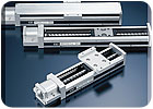
Many companies now recognize the advantages of preconfigured off-the-shelf systems, as opposed to building their own. Ballscrew actuators come in several travel lengths, and at least five stage sizes are available. Once engineers identify the optimum system, they just have to get the right motor.
However, to choose the right system for an application, actuators must be carefully analyzed. Comparisons of the design and sizing of components such as the slide block, raceway, bearings, guide rails, ballscrew, nut and housing materials are critical. They all factor into actuator performance.
The rigidity of a ballscrew actuator is primarily determined by the composition of the guide rail.
Choosing an Actuator
To choose the most effective actuator for an application, engineers must first ascertain some critical information. Factors such as load capacity, operation speed, stroke length, environment, orientation and positional accuracy must be quantified.Besides the size of the ballscrew and guide rails, load capacity depends on the number and size of the recirculating steel balls that roll between the block and the raceways in the guide rails. The manner in which they make contact is also important. One way to boost load capacity is to increase the size of the ballscrew and guide rails. Another way to increase load capacity-without increasing the overall size of the actuator-is to increase the ball circuits.
Most standard ballscrew actuators have one set of recirculating balls on either side of the block. Doubling the number of ball circuits to two on either side doubles the actuator’s load capacity. For example, the maximum load for a 1,380-millimeter-long actuator with two ball circuits is 37 kilonewtons. With four ball circuits, the maximum load is 74 kilonewtons. Similarly, the maximum load for a 100-millimeter-long actuator with two ball circuits is 3.945 kilonewtons. With four ball circuits, the maximum load is 7.89 kilonewtons.
Actuator systems are offered in two or three grades, or levels, of accuracy. “Commercial Grade” is the lowest. Next is “High Grade” or “Standard Grade,” while “Precision Grade” is the highest. When comparing accuracy levels of various systems, engineers cannot assume that all manufacturers’ lowest to highest grades have comparable accuracies. Instead, engineers should compare their published ranges for positioning repeatability, positioning accuracy, running parallelism, backlash and starting torque.
The precision of a linear actuator is affected by how true its guide rails and raceways are and how smoothly the balls recirculate in the block and raceways. Even slight deflections or clearance issues can adversely affect accurate movement and positioning.
For optimum accuracy, it is critical that the guide rail be precision ground. The same can be said of the slide block and ballscrew. Furthermore, the balls within the ball grooves of the raceways must not have clearance that allows them to deflect.
Of the groove designs on the market, the standard choice is between balls that contact the raceway grooves at two points or at four points. A slightly elliptical groove design allows the balls to make contact at two opposing points. However, this design allows a bit of clearance on the sides of the balls that are perpendicular to the contact points. Because of its shape, the four-point contact arch design is called a gothic arch. The gothic arch eliminates any clearance that could lead to deflection and is best-suited for applications requiring maximum precision.
The rigidity of a ballscrew actuator is primarily determined by the composition of the guide rail. Because this is the outer structure of the system, it is the actuator’s support and its rigidity determines how consistently true the grooves of the raceways will be. The thickness and strength of the lower edges of the guide rail are critical to its rigidity. A U-shaped outer rail provides better rigidity against moment loads.
Guide rails positioned lower than the center of the ballscrew also increase rail rigidity. When the ball grooves are closer to the bottom of the rail, the block can carry heavier loads. In combination with the more rigid U-shaped rail, this design even allows applications in which only one end of the ballscrew is supported. It’s also more compact.
The number of ball circuits also affects rigidity. All things being equal (balls, guide rail, block and ballscrew), four ball circuits provide greater rigidity than two ball circuits.
Depending on the application, the speed at which the actuator must travel determines the length of the ballscrew lead. The faster the desired travel time, the longer the lead must be. However, to achieve higher accuracy, it is best to use the shortest possible lead for the job.
There is a direct correlation between speed and lead length. For example, assuming a motor speed of 50 rotations per second, a ballscrew actuator with a 20-millimeter lead could move at a maximum speed of 1,000 millimeters per second. Conversely, the maximum speed of a ballscrew actuator with a 2-millimeter lead would be 100 millimeters per second. The merit of a shorter lead is that it can move a heavier load using a smaller motor, albeit at slower speeds. The motor will still need to be bigger if you want to move a heavy load at maximum speed, however.
Ballscrew actuators are available with metal covers. However, engineers should make sure there are no gaps between the cover and the guide rails. This would be unsuitable for environments where liquids or particulates could enter the system. Though usually a customized option, accordion-style covers are available. They are impervious to fluids and particulates. They replace the metal cover and shield the entire guide.
