Test and Inspection
Advanced Leak Test Methods
Leak testing is an engineering challenge. On one hand, engineers must meet stricter leak rate standards. On the other, they have to make the leak testing process less costly and less dependent on operator skill. To meet this dilemma, engineers must understand all aspects of the leak testing process.
What is a product leak? This common term is not always well-defined. A product leak is material flow from or into a product (a control volume) during a given time, in excess of allowable limits. Product leaks are caused by open flow paths, such as pinholes, broken seals or material porosity. In most cases, a product leak is a very small flow.
The process of quantifying and eliminating a product leak is called leak testing. In the pharmaceutical, medical and food industries, it is called package or seal integrity testing. Leak testing requires the measurement of very small flow rates of a gas or liquid. In some cases, the leak flow rate is correlated to a "virtual pinhole," to quantify the size of potential defects. For example, to prevent contamination, a sterilized medical package must be sealed such that a "virtual pinhole" in the product is smaller than the size of the smallest micro-organism (commonly 0.2 micrometer in diameter). This theoretical pinhole dimension and the leak flow rate are correlated to each other.
Unfortunately, great confusion exists when measuring leaks. Leak flow can be described as volume leak flow or mass leak flow. Volume leak flow is the rate of volume change over time. The most common way to describe leak flow, it is measured in volume units over time, such as cubic centimeters per minute or cubic centimeters per hour. Mass leak flow is the rate of mass change over time. It is measured in mass units over time, such as grams per minute, milligrams per minute or micrograms per minute.
The correlation between volume and mass leak flow is given in the equation:
m = Q * p
In this equation, m is mass flow, Q is volume flow, and p is density, measured in milligrams per cubic centimeter.
Because most leak flow measurements involve gas flow, we can further calculate density based on the gas law equation:
p = P/(T * R * Z)
Looking for quick answers on assembly and manufacturing topics? Try Ask ASM, our new smart AI search tool. Ask ASM
In this equation, P is absolute gas pressure in pounds per square inch--absolute (psia) or kilopascals--absolute; T is absolute temperature in degrees Fahrenheit or Rankin (R); R is the specific gas constant; and Z is gas compressibility, which is dimensionless. For most applications, Z can be assumed to be 1.
Unfortunately, there is a third way to describe a gas leak flow, and it often causes a lot of confusion. Known as "standard" flow, it is measured in standard cubic centimeters per minute (sccm) or standard cubic centimeters per second. Standard flow is defined as actual volumetric flow corrected to "standard conditions." Because more than one standard condition exists, we will define a common standard condition as a dry, pure gas at a specific gas density, a pressure of 14.695 psia and a temperature of 529.45 R.
To calculate a standard gas flow for a specific gas, we can use this equation, which is derived from the two earlier equations:
Qstd = Q * [(P * Tstd) / (Pstd * T)]
In this equation, Qstd is standard flow, Q is actual volume flow; P is actual absolute gas pressure; T is actual absolute temperature; Pstd is standard absolute gas pressure; and Tstd is standard absolute temperature.
Why is standard leak flow so confusing? First, it is gas-dependent. For example, 1 sccm of helium has approximately seven times lower mass flow than 1 sccm of nitrogen! Second, many engineers get confused between standard cubic centimeters per minute and cubic centimeters per minute, and they get more confused converting from one unit to the other. Standard flow can be considered "semi-mass flow."
Because standard flow units are not a recognized measurement unit in the SI system and because they are confusing, it is highly recommended to avoid these units of measurement whenever possible.
What Affects Leak Rate?
Many products contain liquids, so using a liquid for leak testing would seem to be a natural choice. However, using common gas, such as air or nitrogen, for leak testing provides a cleaner, more economical and more sensitive test. To understand why gas is more sensitive than liquid, we must examine the relationship between the leak rate from a pinhole, the size of the hole, and properties of the fluid.
A common model, known as the Hagen Poiseuille equation, can describe a leak flowing through a pinhole:
Q = C * (d4 / l) * (DP / µ)
In this equation, Q is the volumetric leak flow rate in cubic centimeters per minute; C is a constant, defined during calibration; d is the pinhole diameter in centimeters; l is the length of the flow path in centimeters; DP is the pressure differential across the flow path, or the difference between the internal pressure of the product and ambient pressure in kilopascals; and µ is fluid viscosity in micropascal-seconds.
This equation clearly shows that a leak is a volumetric flow, and it is influenced by three main factors.
First, it depends on the defect geometry, mainly the pinhole diameter and, to a lesser extent, the length of the flow path. Therefore, measuring the leak flow rate is a nondestructive way to determine defect size. The leak flow rate is correlated to the defect size.

Second, leak flow depends on the properties of the fluid, mainly viscosity. The higher the fluid's viscosity, the less it will leak, given the same defect and differential pressure. It's important to note that viscosity depends on temperature. Therefore, using air instead of liquid for leak testing increases test sensitivity. For example, at room temperature (68 F), a leak test with nitrogen will be 55.7 times more sensitive than water and 1,248 times more sensitive than transmission oil, due to the viscosity ratio of nitrogen to water and oil at room temperature.
Finally, the leak flow depends on the pressure differential across the flow path. Increasing the differential between the internal pressure of the product and the ambient pressure will increase the volumetric leak flow rate, until the gas flow velocity reaches the speed of sound and the flow becomes "choked." From that point, increasing the pressure does not increase the volumetric flow rate. However, increasing the pressure will increase the gas density, resulting in higher mass flow for the same volumetric flow rate.
The Hagen Poiseuille equation shows that the volumetric leak flow rate does not depend on gas molecular weight, but on gas viscosity. Therefore, we cannot say that helium leaks four times more than nitrogen from a given defect at a given pressure, because it is four times lighter than air. In fact, helium viscosity is approximately 10 percent higher than nitrogen at room temperature. Therefore, a given product with a fixed defect and differential pressure will leak less if it is filled with helium rather than nitrogen.
It's important to note that the fluid dynamics models that are used to develop the Hagen Poiseuille equation will change as the size of the pinhole decreases.

Measuring Leak Flow
To measure a product leak, we need to measure the leak flow rate. Two possible approaches can be used: indirect, or calculated, leak flow rate measurement and direct leak flow rate measurement.
Before new technologies were available to directly measure very small leaks, most leak measurements were performed indirectly. Common methods included bubble testing for large- and medium-sized leaks, pressure decay testing for medium-sized leaks, and trace gas concentration measurement for very small leaks.
In bubble testing, the product is pressurized and immersed in water. The operator then counts the number of bubbles escaping from the product in a given time. Liquid surface effects, operator attention and leak variations make this test very subjective and messy. However, because the cost of instrumentation is minimal, this method is still used. Indeed, many test procedures define a "maximum allowable number of bubbles per minute." This is unwise. Because of the subjectivity of the test, bubble rates do not correlate well with leak flow rates. Bubble testing should only be used to define the point of a leak and not to quantify it.
In pressure decay testing, the product is pressurized and then monitored to see how the pressure changes over time. This pressure change can then be correlated to the leak flow rate. The pressure change can be measured via a pressure transducer, or by comparing the pressure differential between a "master part" and the unit under test.
Understanding how to correlate this indirect measurement to the leak flow rate is extremely important. Although most leak test instruments calculate leak flow rates automatically, misunderstanding the theoretical basis behind those calculations often yields significant errors in leak measurements.
The pressure decay of a given control volume (the volume of the unit under test and the connecting tubes) can be used to calculate leak flow rate using the following equations:
Mass leak flow rate:
m = (ðp / ðt) * [V / (Z * R * T)]
Volumetric leak flow rate:
Q = ( ðp / ðt) * (V / P)
In these equations, m is mass leak flow rate in grams per minute; Q is the volumetric leak flow rate in cubic centimeters per minute; (ðp / ðt) is the pressure decay rate in kilopascals per minute; V is the control volume in cubic centimeters; P is the average absolute gas pressure during the test in kilopascals--absolute; T is the average absolute temperature in degrees Rankin; R is the gas constant; and Z is gas compressibility, which is dimensionless. For most applications, Z can be assumed to be 1.
These equations indicate that the pressure decay method is sensitive to the volume of the test part and the pressure decay rate. Any correlation between the leak flow rate and pressure decay must be performed with the same volume that was used during product testing. In addition, engineers must allow enough time for a steady decay to develop. The pressure decay rate is temperature-sensitive, because gas density depends on pressure and temperature.
Pressure decay instruments can detect leaks at sensitivity rates equivalent to their pressure decay measurement sensitivity. From the conversion equations, it's clear that the larger the product volume, the less sensitive the instrument will be. Engineers must use these equations to establish their measurement requirements. In general, the pressure decay method cannot detect very small leak rates.
In the trace gas method, the product is pressurized with a trace gas, and the concentration of that gas leaking out around the product is measured. Helium is the most common gas used in this process. Helium is an excellent trace gas, because it exists in the environment at a concentration of 4 to 5 parts per million. Helium is also inert. It will not damage the product, the way that more active trace gases can. However, helium is expensive. In many cases, continuous test operations with helium can cost more than $100,000 per year.
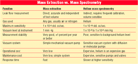
Two types of helium leak detectors are commonly used. Helium sniffer probes are used mostly to indicate the point of leak. Helium mass spectrometers are used to find very small leaks.
In helium mass spectrometry, the part is pressurized with helium and exposed to a very high vacuum (20 to 50 militorr). The helium concentration around the part is then measured over time. The correlation between the helium concentration change (in parts per million per second) and leak flow rate is usually found using leak orifices, charged with helium, that have a known leak rate at a given pressure. This correlation is a simple linear correlation in which the zero, or offset, is assumed to be the background helium level. To maintain a low level of background helium concentration, it's important to thoroughly and continually evacuate the test helium when using this technology. Many helium mass spectrometers are very sensitive to gross leaks and saturation.
With all its drawbacks, helium mass spectrometry is the only method for measuring leak rates of 1*10-7 standard cubic centimeters per second or less.
Direct Measurement Methods
Two new methods of direct leak flow rate measurement have been developed: direct mass leak flow measurement and mass extraction measurement. Both are based on the mass conservation law of physics:
min = mout + dm
In this equation, min is the mass flow supplied into the product under test; mout is the mass flow leaking out from the product under test; and dm is the additional mass accumulated within the product during test time. In a steady state condition, when pressure and temperature within the product under test are constant, dm is 0. Therefore, the mass flow supplied into the product equals the amount of gas leaking out.
Both direct leak testing methods are based on a new flow measurement technology known as accelerated laminar flow technology. Together with built-in pressure and temperature sensors, accelerated laminar flow technology is the basis of a new type of leak detector called an intelligent gas leak sensor (IGLS). The IGLS can measure volumetric leak flow or mass leak flow at very small rates.
Direct mass leak flow measurement has many advantages. It does not require correlation and frequent calibration. It is independent of part volume, configuration or helium background levels, and it's not sensitive to product or environmental temperature changes. Because there is no need to wait for pressure decay, test time is faster.
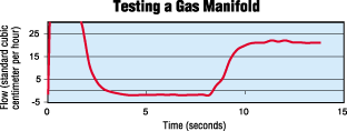
The IGLS measures the make-up gas required to maintain a steady pressure state in the product under test. To start the test, the product is quickly pressurized to a steady state condition. A short time is then allowed for flow to develop. The leak flow is the make-up for the gas that leaked out. The IGLS holds the pressure constant, while measuring the leak mass or volume flow. For a short time (1 second or less), the leak flow values and test pressure are compared to the preprogrammed set value and a pass-fail decision is made. Once readings reach steady state condition, or no change of flow vs. time, actual test time is very short. This not only saves time, it minimizes the effects of product temperature variations during test time.
Because direct mass flow measurement is independent of product volume, it is simpler to specify its measurement resolutions. Current technology offers leak flow measurements as small as 12 micrograms per minute and as large as 1 liter per second.
In mass extraction, the amount of total mass or mass flow of gas extracted from a product is measured while the product is exposed to a vacuum. This method is extremely sensitive and can replace helium mass spectrometry up to a level of 1*10-6 standard cubic centimeter per second, or 0.15 micrograms per minute, at 1 torr vacuum. The ability to use normal air dramatically simplifies the test and saves the cost of expensive trace gases. It can also perform nondestructive tests on products that cannot be filled with trace gases, such as sterilized medical packages.

Mass extraction technology is based on the fact that a small amount of gas leaking from a product expands under vacuum due to low gas density, resulting in a higher volumetric flow rate compared with barometric conditions. Because the IGLS measures very small flow rates and converts them to mass flow, high sensitivity is achieved.
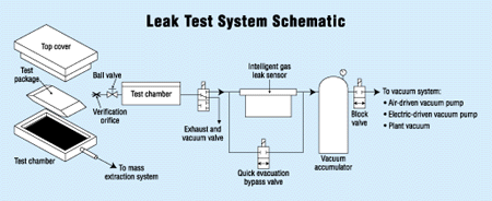
During the test, a vacuum is applied to the internal cavity of the product, or the product is placed within a vacuum chamber. A quick-evacuation valve generates vacuum in the chamber faster, bypassing the IGLS. Once the valve is closed, the amount of mass flow and total mass extracted (in micrograms or 10-6 standard cubic centimeters) is measured. The amount of mass extracted is the mass flow during test time leaked from the part. This is proportional to a minimum capillary flow path diameter. The level of sensitivity is directly proportional to the vacuum applied. Absolute pressure (or vacuum) can be as low as 0.5 torr.
For more information on leak testing, call ATC at 317-328-8492, visit www.atcinc.net.
Looking for a reprint of this article?
From high-res PDFs to custom plaques, order your copy today!


