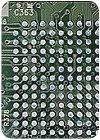
It's now common knowledge that lead-free solder does not wet surfaces as well as traditional tin-lead solder. Among other consequences, this fact is affecting how assemblers rework ball grid arrays (BGAs).
There are two ways to resolder a BGA on a printed circuit board (PCB) assembly. In one method, the solder balls are placed on dots of solder paste. In the other, the solder balls are placed on dots of liquid or paste flux. The question is: Which works better with lead-free assemblies?
The issue of whether joint reliability is better when BGAs are soldered with solder paste or flux paste is controversial. Some studies indicate that the shape of the solder joint has a greater impact on reliability than the volume of solder in the joint. Other studies claim that the extra metal provided by the solder paste will produce stronger, more reliable joints, assuming the joint geometry is correct. However, the additional metal provided by the solder paste at a typical print thickness is usually minimal compared with the amount of metal provided by the balls themselves. The paste actually has little effect on the characteristics of the joint.
Another issue is whether the use of solder paste can improve the yield of the BGA rework process compared with the use of flux only. Coplanarity can be critical during the rework process. If the solder balls of the BGA are not coplanar, it can result in an open connection-a ball that has not contacted and wetted the land while surrounding balls have made contact.
Many factors can affect coplanarity. Variations in surface finish height, warp in the board, and warp in the device itself can create coplanarity problems. The use of solder paste may help to overcome variations in solder ball height.
Finally, some evidence indicates that solder paste may have an edge over flux alone when laser-drilled microvias are present in the BGA lands. The paste reduces voiding and prevents loss of solder ball volume as a result of filling the via.
Settling the Issue
We designed a study to get a definitive answer to the paste vs. flux question. We also wanted to determine whether variations in the dimensions of the BGA lands adversely affected the reliability of reworked BGAs.
To reduce expenses and simulate a very common BGA package, we selected a lead-free, daisy-chained, plastic BGA-256 for the study. The solder ball diameter for this device was 0.76 millimeter, with a pitch of 1.27 millimeters.
The test PCB had a corresponding daisy-chained land pattern to allow for electrical testing once the BGAs were installed. The boards were supplied in eight-up arrays to facilitate testing. Eight arrays (64 boards) were fabricated with lands 0.55 millimeter in diameter, as an example of small lands. Eight arrays (64 boards) were fabricated with lands 0.84-millimeter in diameter, as an example of large lands. The PCBs were fabricated from standard FR-4 laminate, 1.57 millimeters thick. Liquid photo-imageable solder mask was used to cover with bare copper traces. The surface finish was immersion silver.
Each board had a unique identification label. Lead-free solder was applied to all the BGA land patterns on all the test vehicles, then wicked off. This process eliminated the need to test different surface finishes, and it created an accurate representation of a rework site that had been cleaned and readied for BGA replacement. An additional advantage was that we were able to match the solder paste to the surface finish to provide the best opportunity for wetting.
We used laser-cut stainless steel stencils to print solder paste on two sets of boards (large and small lands). We manually applied no-clean flux paste to two other sets of boards (large and small lands). The stencils were 0.2 millimeter thick, and the apertures were cut 1-to-1 for the two different land diameters. The solder paste was a no-clean, lead-free alloy consisting of 96.5 percent tin, 3 percent silver and 0.5 percent copper.
After the solder paste was printed on the boards, the BGAs were placed using automated equipment. The entire array was then processed through a convection reflow oven with a peak temperature of 240 C. After reflow, the boards were X-rayed, visually inspected and electrically tested for continuity through the daisy-chained pattern.
Results
The first-pass yield for the paste-printed BGAs was 100 percent, while the first-pass yield for the flux-only BGAs was 87.5 percent.
Testing was accomplished in a thermal chamber with ambient humidity. The assemblies were subjected to a low temperature of -25 C and a high temperature of 125 C. The dwell time at each extreme was 30 minutes, and the ramp time to each extreme was 30 minutes.
To date, the samples have completed 672 cycles. To this point, there have been no failures in any of the groups. Testing will continue to at least 1,000 cycles in an attempt to create failures.
Our data indicate that variations in the dimensions of the BGA lands had no detrimental effect on reliability for a variety of processing methods in normal environments. With the exception of first-pass yield, both the solder paste and the flux paste rework methods performed well.