Because of their complexity, most miniature circuit breakers are produced using manual and semi-automatic equipment in Mexico and other low-cost labor markets. In fact, the Square D facility in Lincoln, NE, is one of the last plants in the United States that still makes them. The Lincoln plant has this distinction because of its successful automation strategy.
Square D's QO miniature circuit breaker is the best such device on the market. Available for 30 years, it performs better and offers more features than most competing models. Indeed, the QO has been around so long because it provides more features per dollar of sales. It's not the lowest cost circuit breaker on the market; it's the premium model. The QO breaker is clearly a symbol of the company and the "breaker to buy."
However, more features means more parts and a more complex design. And that equates to higher manufacturing costs. We had to find a way to make the circuit breaker less expensive to produce. If not, we might have to move production to a low-cost labor site, and we wanted to avoid that fate. Not only did we want to keep manufacturing jobs here, but we were also concerned that the quality of the circuit breaker might diminish if we assembled it in Mexico.
One way to lower production costs is through automation. So in 1993, we began a project to automate fabrication and assembly of the circuit breaker. The project had the blessing of management--with one caveat. The product's 30-year reputation could not be jeopardized for any reason. If we changed the design of the circuit breaker to facilitate automation, we could not affect its performance, look, feel or sound. (Some even said it had to smell the same!) We were going to have to act carefully, because several design problems inhibited sensible automation.
Besides management's design concerns, we had another issue to wrestle with. Past automation programs at Square D had very little affect on cost. They merely traded direct labor for equipment maintenance labor. When we contacted automation vendors for the QO project, many of their proposals offered little to contradict our previous results. For example, some proposals included manipulators that merely duplicated the manual functions already being performed. We wanted to avoid that type of solution.
In the end, the automation solution we developed enabled Square D's Lincoln plant to keep producing the lowest cost, best quality circuit breaker available today.
Ground Zero
In planning our automation project, we had several goals. First, we wanted to redesign the circuit breaker to facilitate automated assembly. We wanted practical tooling solutions. We wanted to identify and solve any potential quality problems with the product. We wanted to integrate fabrication into the solution. And, we wanted to reduce the specifications for the circuit breaker's fabricated components.If our automation project was to succeed, we had to improve the 30-year-old design of the circuit breaker. We faced a number of problems. For starters, few of the assembly operations could be done on the Z axis. That is, few parts could be inserted straight down, which is the ideal assembly motion. There was too much interference between parts and too little clearance.
The pin between the flag and the trip lever was not accessible with the flag in place. The trip lever was hard to locate accurately, and the pin could not find the hole consistently.
The tension spring was not designed for automation. The spring was interleaved with the blade and handle. The hooks were threaded into holes or slots on both ends. Inserting the spring was not a Z-axis assembly operation.
The blade interface to the handle had the blade straddling the trip lever and in-between the handle. This assembly has three parts interleaved, one inside the other. This was not a Z-axis assembly operation.
The armature extension interleaved with the pigtail, and the armature pivot interleaved with the yoke. Again, neither was a Z-axis assembly operation.
Finally, the flexible connector and the compensater were delicate parts--perhaps too delicate for automated assembly.
Revised Design
Due to excessive design constraints, the issue of pin accessibility was solved through tooling methods. The flag is now pre-assembled on the pin and then set into the breaker as a subassembly.CAD analysis indicated the hole for the pin could be modified slightly, but not enough to allow for accumulated part tolerances. So, locating features were added to the assembly head to force the trip lever into a known position.
The tension spring and its attachment points were redesigned for Z-axis assembly. The eyes for the springs were closed, and tangs or tabs were added to the mating parts for Z-axis assembly. Extensive analysis was completed to balance the eye diameter (it had to be as large as possible) with endurance cycles of the spring (we wanted as many as possible). The eyes of the spring were sized to accommodate assembly needs, plus endurance and force.
The compression spring was redesigned to eliminate tangling, and tooling was developed to compress the spring during assembly. For this problem, we relied heavily on assistance from our assembly machine builder and the spring manufacturer.

The armature and the yoke were redesigned. However, the new armature was too delicate to feed with feeder bowls, and entanglement problems would have been enormous. Tooling improvements solved the problem.
A fairly straightforward redesign solved the problem with the armature pivot. The armature is now assembled with the yoke and trip lever already in the base.
We tackled the issue of handling flexible and delicate parts in several ways. First, we redefined the order of assembly to install the flexible lead first and assemble the other parts around it. We placed the string assembly into the base of the breaker at the fabrication station. We found material handling methods that can deal with two parts connected with a flexible wire, as well as manage delicate parts that normally tangle. Finally, we eliminated deforming operations.
Integrating Fabrication
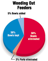
In most automated assembly programs, little effort is spent on integrating fabrication into the system. Normally, the parts are designed first, and then the automation vendor is consulted about feedability requirements. But, part specifications for product performance often differ from those for automated feeding. So, feeding requirements are added to part drawings that are already cluttered with numerous specifications. The part grows more complex, driving up part cost faster than the gain in reducing assembly labor. We had to stop transferring automation requirements to fabrication.The QO circuit breaker was in production with slight modification for 30 years. Originally, the circuit breaker was produced with manual assembly, manual welding, stamping and plating operations. Over the years, feeder bowls were added to these operations to "automate" them. Feeder bowls were the technology of choice for the time, but they yielded islands of automation that eventually limited output. The productivity of the equipment topped out at 30 to 40 parts per minute. Overall equipment effectiveness ranged from 35 percent to 50 percent, when one tender was used to run four stations. This did not support high-volume production.
Fifteen years ago, when our first assembly machine was introduced, an era of feedable parts quality began. Dimensions, tolerances and control techniques became the discussion of the day. The plant was very successful at improving part quality. The productivity of the assembly machines began to improve slowly. It was time to think about alternatives to the feeder bowls.
In many cases, feeder bowls provide the only viable solution, but in our situation, many of them were unnecessary mixing mills. Even when all critical part dimensions were in control, machines with feeder bowls were still down 80 percent of the time, due to jamming and other feeding problems. Machines with 10 or more feeders had overall equipment effectiveness ratings of 40 percent to 60 percent!
Feeder bowls incurred additional production costs beyond those related to downtime and the tight tolerances we had to hold on parts. First, we often had the part in the desired assembly orientation during stamping. By putting the parts into feeder bowls, we threw away that orientation and had to reorient the part in the bowl. Feeder bowls also create inventory, because parts have to be transferred between stations in containers. And, each time parts are handled, they can get distorted. Finally, parts from different stamping and plating runs could be mixed together. We wanted to avoid that for quality control reasons.
Further investigation into the cost of feeding parts led to the specifications on our fabrication prints. The feeding requirements were definitely complicating our fabrication process. We decided to divide the quality variables on our parts drawings into two categories: those that really affected product performance and those that affected feeding and handling. We determined that 90 percent of the tolerances on the prints had little or no effect on the product.
We also examined variables that were on the prints just to control component dimensions, which were believed to stack up to final dimensions. This was a difficult analysis. Most people could not grasp the reason for such analysis. It seemed counterproductive after years of geometric dimensioning and datum discussions.
We recommended the following steps for re-evaluating the design of fabricated parts:
- Analyze the reasons why certain dimensions exist.
- Reduce the database to critical dimensions.
- Implement solutions that focus on those critical dimensions.
- Use subassembly dimensions to reduce overall dimensions.
- Implement functional gauging.
The Solution
Our automation project was the result of new technology and different ways of thinking about fabrication and assembly. Now, instead of fabricating discrete parts that are eventually dumped into feeder bowls, we stamp parts on a continuous metal carrier strip and assemble other parts directly onto the stamped parts, without removing them from the carrier strip.The punch press's function was expanded and embedded in the assembly line. Raw stock goes in, and assembled product comes out. At the time, this was new technology, but today, there are lots of articles on in-die tapping, in-die welding and in-die assembly.
The assembly line now begins with a seven-step process:
- Stamping of the yoke.
- Stamping of the bimetal.
- Welding of the bimetal to the yoke.
- Fabrication of the pigtail.
- Welding of the pigtail to the bimetal.
- Fabrication of the terminal.
- Welding of the terminal to the bimetal. Wrapping of the pigtail.
Plant inventory for the automated line went from months to days. Product cost from the Lincoln plant is lower than that from Mexico or Thailand, if duties are removed. Seventy percent of the plant production is handled by this technique. Plant capacity tripled, and the number of employees has not changed.
