A superficial consideration of which methods to use for leak testing medical devices might suggest that there is no difference between, say, testing a pump to deliver insulin and testing a pump to deliver motor oil. In fact, the business realities that affect how medical products are designed and assembled do influence both the choice of leak testing technology and how this technology is applied.
Given the mandates of the FDA's Good Manufacturing Practices and the threat of medical malpractice lawsuits, the reliability of leak testing technology is critical for medical device assemblers. Machine builders that take shortcuts with testing technology will be unable to deliver the gauge repeatability and reproducibility (gauge R&R) that is necessary to meet regulatory and legal requirements.
Documenting gauge R&R begins with an understanding of what the concept means.
Statistical process control (SPC) is important for documenting the precision of the various instruments used to measure and test parts and assemblies. Too much variation in a measuring system can mask problems in the manufacturing process.
Measurement errors can result from five factors:
- Accuracy-comparison of the measurements to a known standard.
- Repeatability-variation of repeated measurements made by one operator on a master part or parts.
- Reproducibility-variation of repeated measurements made by more than one operator on a master part or parts.
- Stability-variation in accuracy over time.
- Linearity-variation in accuracy within the measuring range.
For legal or regulatory reasons, assemblers may be asked to document the leak detector's precision through these accuracy, stability and linearity controls. Assemblers that rely on mechanical means for calibrating leak testing instruments may be caught short, as will those that use off-line calibration. Assemblers will be better served by calibrating and validating their leak testers on-line using solid-state calibration technology, automatic temperature compensation during testing, and similar controls that minimize or eliminate the need to shut down the line for recalibration. Not only will these methods maximize uptime, but they will also carry the most weight in legal and regulatory proceedings.
Although SPC is an important quality assurance tool, the most useful measure of gauge performance is gauge R&R. The lower the gauge R&R, the more the test results can be relied on. Generally speaking, a gauge R&R of 10 or less is acceptable. A gauge R&R of 11 to 30 may be acceptable for medical devices in which the health of the patient would not be jeopardized by a leak that is higher than it should be. For nearly all applications, a gauge R&R greater than 30 suggests that the leak testing process is unreliable.
It's important to note that medical devices do not necessarily require a leak testing process with an extraordinarily low gauge R&R. However, assemblers are required to demonstrate that the instrument's gauge R&R has been measured and documented.
Real-World Testing
Perhaps the greatest error assemblers make when determining gauge R&R is to equate the gauge R&R of the test instrument with the gauge R&R of the actual test process on the assembly line. Instruments in a laboratory are easier to control than instruments in the real world of the assembly line. As a result, it's imperative for machine builders to work closely with leak-testing experts when designing test-intensive assembly processes. Failure to understand the real-world requirements of various leak testing methods will lead to unreliable results.For example, poorly designed fixtures for leak testing will create a significant gap between presumed gauge R&R of the test instrument and the gauge R&R of the actual test process. Fixturing problems are apt to occur when testing is an afterthought to the assembly process, instead of the starting point. Fixtures must be designed to prevent problems such as seal creep, adiabatic effects on test readings, and part distortion during the test process.
When leak testing medical devices, it's critical to test the parts in a manner that is consistent with how they will actually be used. Whenever possible, production parts should be used during test development. During testing, the parts should be fixtured in the same orientation as they will be used with a patient.
The fear of litigation should not compel medical device assemblers to use testing methods with tighter tolerances than necessary for the application. For most medical devices, the choice of leak testing method is between helium mass spectrometry and mass flow.
If the device must contain a noxious or hazardous material and the leak to be detected is below 0.001 standard cubic centimeter per second (sccs), a helium mass spectrometer is required. In this method, the part is pressurized with helium or a mixture of helium and air inside a test chamber. The chamber is then evacuated, and a mass spectrometer samples the vacuum chamber, looking for helium. This technology can measure leakage as low as 0.000001 sccs. This accuracy is largely due to the sensitivity of the mass spectrometer.
However, if the medical device does not involve noxious or hazardous materials, there is little reason to incur the high cost of helium-based test methods. For helium-based testing, the test chamber and circuit components are very expensive, especially for testing large part volumes. And, of course, the helium itself is an expense. These costs are usually prohibitive for any application that does not require tests for leaks less than 0.01 sccm.
For most medical devices, mass flow leak testing is adequate, and the cost savings is considerable compared with helium-based testing. In the mass flow method, the test cavity is pressurized, and any leakage is naturally compensated for by air flowing into the test part. The air can come from a reference volume reservoir that is pressurized simultaneously with the test part. Or, the air can come from a supply line controlled by a regulator. The air that flows in to replace leakage crosses a mass flow sensor and is measured in standard cubic centimeters per minute (sccm).
Mass flow leak testers can be used for any application that must detect leaks greater than 0.5 standard cubic centimeters per minute. In many cases, mass flow testers can be used to detect leaks greater than 0.3 sccm.
Using helium mass spectrometry to detect leaks between 0.3 and 0.5 sccm may unnecessarily add cost to the assembly process. Mass flow leak detectors can handle the job, as long as fixtures are well-designed, test stations are sufficiently rigid, and the reference points for testing are correct. It's also important to use high-quality mass flow instruments that are customized for the application. If engineers take shortcuts with the quality of sensors used in mass flow instruments, it will inevitably result in unacceptable gauge R&R's.
To meet legal and regulatory requirements, detailed and complete documentation of leak testing is highly advisable. The monitoring software of the leak testing system must record all test results and track gauge R&R. Indeed, these are the minimum requirements for data processing of leak testing results. For maximum production efficiency, assemblers should use monitoring software that can display trend graphs and histograms of accumulated test results with upper and lower specified limits. The software should also store all data for future SPC tracking.
Making an Aerator Leak-Proof
Many innovative medical devices are first conceived by clinicians who see room for improvement in standard medical practice. However, that's only half the story. The other half lies in turning those ideas into workable designs, making the parts, and assembling them into quality products.Such was the case with a new breathing apparatus developed by Apotheus Laboratories Ltd. (Lubbock, TX) and Industrial Molding Corp. (IMC, Lubbock).
Anesthesiologist Randy Hickle, MD, noticed that patients coughed frequently while recovering from anesthesia. This coughing exposed other patients and hospital staff to airborne infectious diseases. Dr. Hickle's idea was to create a disposable plastic device, an aerator, that would channel a patient's exhalations to the hospital's vacuum system.
Although the aerator's main function is to safely remove a patient's exhalations, an overriding factor in its design was to allow patients to breathe effortlessly. IMC solved that issue by creating a three-piece polycarbonate check valve. The valve features a lightweight plastic disk that floats free in a cage over a circular seat in the valve's base. When air flows upward, the disk lifts open. When there is downward airflow or no airflow, the disk drops closed.
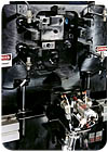
The tolerances for the valve seat are tight. The seat must provide a good seal, but it can't stick, even when it's wet from exhaled moisture. IMC's engineers knew that each unit would need to be tested to document airflow and a lack of leaks. Moreover, because the finished product cannot be reopened, each valve would have to be pretested before it was sealed inside. IMC partnered with InterTech Development Co. to provide the test equipment.
InterTech designed a custom system with two test stands: one for the valves and one for the fully assembled aerators. Both stands use InterTech's M-1035 mass flow leak detector for quick, direct measurement of leakage, independent of pressure and volume. The unit's transducer can test volumes from less than 1 cc to more than 10 liters with an accuracy of ±0.05 sccm.
The fixtures for each stand were key to the system's success.
At the valve testing stand, newly welded valves are put on a doughnut-shaped fixture that is not clamped, to prevent distorting the cage. A vacuum generator built into the test stand supplies a pressure of 11 inches of mercury to a programmable bias regulator inside the M-1035. Under closed-loop control using a remote pressure transducer, the unit creates a vacuum of 0.05 psig through the fixture and part. That low pressure is stabilized for 5 seconds. Any air leaks are then drawn in and measured by the M-1035 mass flow sensor. If a flow rate greater than 50 sccm is detected, a red indicator light turns on, and "reject" appears on the M-1035's display panel.
The fully assembled units are tested in an upright position that recreates the device's orientation in clinical settings. This is necessary because operation of the check valve is gravity-dependent. The test fixture fits the aerator's multiple ports.
Before testing, a programmable logic controller ensures that the fixture is correctly loaded and locked in place. It then steps through an automatic sequence of tests by an M-1035 equipped with three sensors: two high-flow sensors (one positive and one negative) for flow tests, and a bidirectional low-flow sensor for leak tests.
Each aerator chamber has three passages and valves that are first tested for 3 seconds. The assembly is rejected if leakage exceeds 100 sccm. The most critical test is at 0.1 psig for conditions that would allow exhaled contamination in the vacuum chamber. Then, each passage and its check valve are tested for either positive and negative flow rates at 10.05 psig, depending on whether normal operation exposes those chambers to inhalation or exhalation pressure. The assemblies are rejected if the leak rate is more than 50 sccm or the flow rate is less than 10 liters per minute.
A specially sealed aerator is used as a leak-rate standard, in conjunction with InterTech's CalMaster instruments, which automate calibration. The CalMaster and the M-1035 use identical mass flow sensors, and the known leak rate of the standard is shown in sccm on the CalMaster unit display.
Aerators that pass all tests are marked. Later in the assembly process, each aerator receives a bar-coded label identifying the lot from which the unit's valves came. The leak detectors automatically store test data, which is also printed out and stored in files that are kept with each instrument. In this way, the documentation that is so important to medical devices is complete.
