If you've ever used a laptop computer on its namesake location, you know these portable PCs can really put out the heat. If the heat is uncomfortable, you can at least take solace in knowing that somewhere inside your computer, a thermal interface material (TIM) is helping to keep the microprocessor cool and functional.
A TIM is placed between two parts to help conduct heat from one surface to the other. Inside a microelectronic package, TIMs transfer heat from the silicon chip to a heat spreader. Outside the package, TIMs conduct heat from the heat spreader to the heat sink. Yet for such a simple job, electronics assemblers have a bewildering array of options for TIMs, ranging from the low-tech, like grease, to the cutting-edge, such as carbon nanotubes and microelectromechanical systems (see the sidebar at the bottom of this page).
Which to choose depends on many factors. How much heat does the package generate? How much thermal resistance can the package tolerate? How smooth are the surfaces of the package and heat sink? Will the microprocessor ever need replacement? Will it need to be electrically isolated from the heat sink? Even the geographic location of the final assembly can make a difference. A laptop destined for a coffee shop in Helsinki, Finland, may need a different TIM than one for a factory in Kuala Lumpur, Maylasia.
"Engineers should approach the problem [of dissipating heat] as an overall system, as opposed to the TIM by itself," advises George Toskey, electronics market manager for Dow Corning Corp. (Midland, MI). "The TIM, heat spreader, heat sink and fan work together, so the whole system needs to be optimized, and not just for performance, but for cost, too. In many cases, if you use a better performing TIM, you might not need quite as exotic a heat sink-or vice versa."
Material Options
Thermal grease is one of the best performing TIMs. It consists of thermally conductive particles, such as boron nitride or aluminum, suspended in a silicone or hydrocarbon oil carrier.
Besides being an excellent conductor of heat, grease has several advantages compared with other TIMs. It does not have to be cured, and it does not have to be heated to work. Because it can flow, grease is good for joining two materials with different coefficients of thermal expansion. Grease doesn't bond to the parts, so the heat sink can easily be removed for servicing. Grease wets surfaces very well and produces the thinnest possible joint line.
"Besides the bulk conductivity of the TIM, the thickness of the bond line has the biggest impact on heat transfer across the interface-the thinner the better," says Toskey.
Ironically, many of these favorable characteristics can also be seen as disadvantages. Grease doesn't bond, so clips or screws are needed to keep the heat sink in place. Grease flows, so it can escape from the joint. "Greases are messy," warns Jason Brandi, global product manager for thermal management materials at Henkel Corp. Electronics Materials Div. (Irvine, CA). "They can dry out. They can migrate. For long-term use, they're not recommended."
Phase-change materials perform as well as grease but without the mess. A phase-change material is a polymer infused with thermally conductive particles. The polymer changes from a solid to a high-viscosity liquid when it reaches a particular temperature. Like grease, phase-change materials conform well to irregular surfaces. But, like grease, phase-change materials do not bond to parts, so mechanical fasteners are necessary to attach the heat sink.
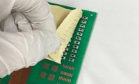
Phase-change materials are typically supplied in precut shapes on a roll of tape. Small pads of the material are peeled off the roll and affixed to one of the parts. Last year, however, Honeywell Electronic Materials (Tempe, AZ) introduced a screen-printable phase-change material. This enables electronics assemblers to apply phase-change materials in a variety of shapes to match the design of the chip.
Thermally conductive elastomeric films or pads are similar to phase-change materials, only without the phase-change feature. They consist of a substrate, such as woven glass fibers, dielectric film or aluminum foil, that has been coated with a silicone-based emulsion infused with heat-conducting particles. To maximize the effectiveness of films or pads, the heat sink must be held tightly against the chip with a fastener. As pressure increases, the elastomeric material fills more of the voids in the part surfaces and thermal resistance decreases.
"The advantage of film is that it's very easy to process," says Toskey. "You can cut nice shapes out of them. But, film doesn't perform nearly as well as phase-change materials or grease."
Thermally conductive adhesives are another option for coupling microprocessors with heat sinks. The major advantage of adhesives is that they hold the heat sink in place without the need for mechanical fasteners. Epoxies, silicones and acrylics are all available in thermally conductive formulas. They can be one-part or two-part materials ranging from free-flowing liquids to nonflowing pastes.
"Adhesives wet the surfaces of the parts like grease and phase-change materials, but they don't perform as well thermally," says Brandi.
One disadvantage of adhesives is that they often require curing with heat or ultraviolet radiation. This adds time to the assembly process and could potentially damage sensitive components.
Earlier this year, Henkel introduced a two-part thermally conductive adhesive, Loctite 3875, that addresses that shortcoming. The acrylic adhesive does not require precise metering or mixing. One part is applied to the package; the other part is applied to the heat sink. When the two parts are assembled, the adhesive immediately begins curing. At room temperature, the bond reaches fixture strength in 3 to 5 minutes and fully cures in 24 hours. "As soon as you put the parts together, you can throw the assembly in a box and ship it and not worry about them coming apart," says Brandi.
The adhesive can be applied with automatic dispensers or screen printers. Parts A and B are different colors, and they change color when mixed. This prevents errors, such as applying Part A to both the package and the heat sink. The two parts need not be dispensed in equal amounts. "It could be 60:40 or 40:60," says Brandi.
The thermal conductivity of the adhesive is 1.75 watts per meter-Kelvin. The adhesive is also available with glass beads mixed in. The beads, which are 7 mils in diameter, ensure that bond lines will be a consistent thickness.
Double-sided tape is another option for bonding heat sinks to chips. Tapes consist of a substrate, such as a dielectric film or aluminum foil, coated on both sides with a thermally conductive pressure-sensitive adhesive. Silicone-based adhesives are preferred for metal-to-plastic assemblies, while acrylic based adhesives are preferred for metal-to-metal joints.
"You don't have to cure tape, which is good. But, their thermal performance is not even close to that of liquid adhesives," says Brandi.
Using low-melting solder as a TIM is an emerging application, especially for attaching heat pipes to chips in notebook computers. Solder provides the best physical connection of any TIM, and the thermal conductivity of solder ranges from 30 to 86 watts per meter-Kelvin.
"The benefit of solder, by far, is performance-nothing conducts heat better than metal," says Brandi. "But, you do have to reflow the solder, and solder is electrically conductive, so it's not an option for every application."
Choosing a Material
In some cases, a particular aspect of the application will point engineers to one TIM over another. For example, if the manufacturing tolerances for the heat sink and the processor package are relatively large, that would rule out a grease in favor of a gap-filling material. In other cases, the choice is less clear. In terms of cost, the better a material's thermal conductivity, the higher its price tag.
"Any [TIM] can potentially be swapped for another," says Brandi.
Before choosing a TIM, engineers should find out how much heat the processor will generate and how much that heat will adversely affect the reliability of the device. They should also measure the thermal resistance at the interface and determine how much thermal conductivity will be required in the TIM.
Computer modeling is invaluable for understanding how the various elements of the assembly interact. Engineers can also use the software to experiment with different TIMs without spending days or weeks in the lab.
Besides thermal conductivity and thermal resistance, engineers may have to specify the hardness of the TIM, and whether it must meet any standards, such as UL approval. Engineers should also specify whether the TIM must be electrically insulating or electrically conducting. If the TIM is a conductive adhesive, engineers should specify the material's viscosity and curing method.
"With low-end applications, there's not a lot of counseling required," admits Toskey. "The applications are not so closely engineered that you need to split hairs over what level of thermal conductivity you need. It's more about convenience, quality and cost."
The Next Wave
As integrated circuits increase in complexity and power, electronics assemblers will need better and better TIMs. "Thermal management is a big issue, especially for leading-edge processors, so there's always a need for new technology that will improve performance or reduce cost," says Toskey.
Honeywell has developed a new TIM that consists of an array of aligned graphite fibers. The fibers are held in place by a thin layer of adhesive, and the array is encapsulated in a gel-like elastomeric material to prevent broken fibers from escaping the interface.
The fibers create a continuous thermal path from the chip to the heat sink, resulting in high thermal conductivity, even with large gaps. The fibers are 10 microns in diameter and no less than 0.015 inch tall. (Shorter fibers are too difficult to orient.)
Because the length-to-width ratio of the fibers is high, the TIM has a high degree of mechanical compliance, making it ideal for applications such as multichip modules, where variations in interface thickness and coplanarity can be absorbed with little or no thermal penalty.
The material tolerates thermal and mechanical cycling well, and will not pump out or dry out from the interface during use. It has a thermal conductivity of 50 to 90 watts per meter-Kelvin.
The material is produced in sheet form and can be preapplied to any component surface or shape. The component to which it is attached can be disassembled and reworked without having to replace the material.
The TIM is not for every application, however. The graphite fibers are strong in tension and compression, but brittle in shear. As a result, the material does not exhibit good abrasion resistance and is unsuitable for applications that require shear resistance. In addition, the temperature limits of the adhesive and encapsulating material restrict use of the TIM to temperatures under 110 C. A high-temperature adhesive and encapsulant can be substituted, but the thermal conductivity of the TIM will be reduced. Finally, the fibers are electrically conductive, so the TIM cannot be used if the chip should be electrically isolated.
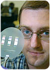
Researchers at Purdue University (West Lafayette, IN) have taken the conductive fiber idea one step further-or rather, one step smaller. They have created a carpet of carbon nanotubes that acts as a TIM.
"The performance that we see with nanotubes is significantly better than comparable state-of-the-art commercial materials," says Timothy Fisher, an associate professor of mechanical engineering who is leading the research. "Carbon nanotubes have excellent heat-conduction properties, and our ability to fabricate them in a controlled manner has been instrumental in realizing this application."
The nanotubes range in diameter from less than 1 nanometer to approximately 100 nanometers. A carpet of the nanotubes can be attached to both the chip and heat sink surfaces.
"We say it's like Velcro because it creates an interwoven mesh of fibers when both sides of the interface are coated with nanotubes," Fisher says. "We don't mean that it creates a strong mechanical bond, but the two pieces come together in such a way that they facilitate heat flow, becoming the thermal equivalent of Velcro."
The researchers have found that the nanotube-based interfaces conduct several times more heat than conventional thermal interface materials at the same temperatures. "In some cases, using a combination of nanotube material and traditional interface materials also shows a strong synergistic effect," Fisher adds.
Besides microprocessors, the nanotube material can also be used to cool power electronics in military and other commercial applications. The technology is ready for commercialization and is already being pursued by several companies, including Nanoconduction Inc. (Sunnyvale, CA).
SIDEBAR: Micro-pump Is Cool Idea for Future Computer Chips
Engineers at Purdue University (West Lafayette, IN) have developed a tiny pump that fits on a microprocessor and circulates coolant through channels etched into the chip.
The new device, a microelectromechanical system (MEMS), has been integrated onto a silicon chip that is about 1 centimeter square.
"The most innovative part of the technology is the micro-pump," says Suresh Garimella, a professor of mechanical engineering and director of Purdue's Cooling Technologies Research Center. "Because it's a MEMS pump, we were able to integrate the entire cooling system right onto a chip."
The prototype chip contains numerous water-filled microchannels-grooves about 100 microns wide. The channels are covered with hundreds of electrodes that receive varying voltage pulses in such a way that a traveling electric field is created in each channel. The traveling field creates ions, which are dragged along by the moving field.
"Say every sixth electrode receives the same voltage. These varying voltages from one electrode to the next produce a traveling electrical field that pulls the ions forward, causing the water to flow and inducing a cooling action," explains Garimella. "Essentially, you are pumping fluid forward."
This pumping action is created by a phenomenon called electrohydrodynamics, which uses the interactions of ions and electric fields to cause fluid to flow.
"Engineers have been using electrohydrodynamics to move fluids with electric fields for a long time, but it's unusual to be able to do this on the microscale as we have demonstrated," Garimella says.
The researchers also have added a feature to boost the force of the pumping action. A thin sheet of piezoelectric material, which expands and contracts in response to an electric current, was glued on top of the cover of the liquid-filled channels.
"This material acts as a diaphragm that deforms up and down when you give it a voltage, causing it to push additional flow through the channels," Garimella says. "We have developed mathematical models that show this piezo action enhances the electrohydrodynamic performance."
The diaphragm has enhanced the pumping action by 13 percent in the current prototype, but the modeling indicates a possible enhancement of 100 percent or greater.
"Although electrohydrodynamics has generally not been considered practical for pumping applications due to the assumption that it requires a large amount of energy and does not produce enough motive force for thrust, the method has been shown to be far more efficient for micro-cooling applications," Garimella says. "We have shown that the power input required is in the microwatts, but you can get milliwatts of cooling. In other words, the cooling effect is more than a thousand times greater than the energy needed to drive the system. That's because all we need to do is create enough of a flow to induce cooling."
However, several major challenges remain. "One big challenge is further developing mathematical models that are comprehensive and accurate, because this is a very complicated, dynamic system," Garimella says.
Other challenges include sealing the tiny channels to prevent water leakage and designing the system so that it can be manufactured under the same conditions as any semiconductor chip.


