All too often when designing an automated assembly system, the test requirements for the product are an afterthought. This suboptimal approach compromises gauge reliability and reproducibility. Worse yet, if defects are found, engineers may be unable to diagnose whether their test processes are creating false positives, or if real part defects are the issue.
A better approach is to consider the product’s test requirements up-front-a process I call test-centric assembly. By thinking about the test fixtures, hardware and software at the system level, engineers will increase efficiency, improve production speed and boost yields.
There are considerable advantages to in-process testing vs. end-of-line testing. With each part added to an assembly, it’s value increases in terms of labor and material costs. By integrating testing throughout the assembly process, engineers can avoid adding value to a defective product.
Here are some examples of in-process testing:
* Functional testing to verify electrical, pneumatic and mechanical characteristics.
* Resistance measurements of coils, heaters or resistors.
* Leak testing after ultrasonic welding of two plastic parts.
* Machine vision inspection to ensure that parts are positioned correctly.
* Dimensional gauging after crimping.
* Electrical testing for continuity, voltage, current and contact bounce.
Test-centric assembly requires a specific type of assembly chassis. Engineers must be able to relocate or remove workstations and accommodate test processes with different times. Power-and-free conveyor systems offer flexibility and asynchronous operation. However, they also require fairly complex control systems, and they inherently produce a large amount of work in process.
A more efficient option is a standardized, heavy-duty in-line chassis that facilitates workstation setup and retooling. If some tests require more time than other processes, assemblies can be doubled up at those stations without reducing overall throughput. These are typically small footprint machines: 40 inches wide by 90 inches long for 18 stations.
For larger assembly systems, standard chassis can be combined end-to-end, side-by-side or end-to-side. Servo drives allow engineers to optimize the transfer rate depending on part inertia without mechanical adjustments or swapping out machine components. Each station has its own base plate, so engineers can add, remove or retool any station without disturbing the others.
A key feature for a test-centric assembly system is the ability to track the contents of each pallet and report the condition of the parts to the control system. Is the part present? Has the assembly passed or failed a test?
A test-centric assembly system also needs a method of handling rejected pallets. For example, rejected pallets can continue down the line, ignored by succeeding operations until unloaded at an intermediate position. Rejects can then be sent to a parallel repair line.
Defective Parts or Defective Tests?
The inability to differentiate good assemblies from bad ones usually results from an inadequate understanding of test requirements. This, in turn, produces test processes with poor signal-to-noise ratios. For example, seal creep can create a poor signal-to-noise ratio in a leak testing process. Another example is in-process gauging stations that are insufficiently rigid or do not have the correct reference.Thus, the first requirement for a test-centric assembly system is a thorough understanding of accuracy requirements and the best methods for achieving those results. In leak testing, for example, the choice between methods is often driven by a compromise between cost and performance. There are several methods to choose from-simple pressure decay, differential pressure decay, mass flow and helium mass spectrometry.
Simple pressure decay testing has a lower initial cost, but may be more costly in the long run because of its long cycle times. It’s also unsatisfactory for detecting leaks under 5 standard cubic centimeters per minute (sccm). Differential pressure decay testing is better for detecting small leaks or testing at high pressures, but it’s inadequate for testing assemblies where temperature compensation is an issue.
This does not imply that higher cost test methods are necessarily best. Helium mass spectrometry is expensive-particularly with the high price of helium today-but the cost is rarely justified unless leaks of less than 0.01 sccm need to be detected. For detecting low leak rates, mass flow testing with custom sensors is often preferable, since it offers short test times, compensates for temperature, and delivers the best accuracy for detecting leaks of 0.05 sccm or larger.
The details of how a test is performed are vital for determining if the process is adequate. For optimal results, engineers should build-in regular checks of their test processes. For example, in mass flow testing, it’s impossible to know if a valve is working, because there is zero pressure from atmosphere. A zero leak measurement could be due to a dysfunctional valve or a plugged line. As a result, mass flow testing employs a bias leak that verifies that the entire system is working. If valves are not operating correctly or test seals are insufficient, the bias leak will not be detected as a leak.
Similarly, test systems should be frequently calibrated and validated. Mistakes are often made by relying on error-prone mechanical calibration methods, such as pneumatic valves or small orifices. Test-centric assembly systems use electronic calibration methods, which are faster and more reliable.
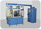
The chassis for this 18-station automated assembly system is designed for easy setups. Each station has its own base plate, so engineers can add, remove or retool any station without disturbing the others.
Fixtures: Test vs. Assembly
It often surprises automation engineers that the fixtures they take pains to create for fastest throughput in assembly often have quite the opposite effect for failsafe testing. For example, if you are driving screws into an assembly, you generally want a fixture with a lot of float. However, such a fixture would be inadequate for leak testing. Similarly, if a welded part is operated under pressure, you want to make sure that if the weld opens up, it leaks to the atmosphere. If the fixture restrains motion in the weld, it is masking the leak.Another issue with leak testing is part damage during sealing. A simple clamp and cylinder can eliminate deflection of the parts during testing, but they can also crush the assembly. Too much clamping pressure can also mask leaks.
The addition of helium into the leak testing process poses another set of challenges for fixturing. You must take care to avoid trapping any helium in the seals. Any tracer gas that hangs around after the test sequence will contaminate the following test. This is not the case with dry air testing. On the other hand, deflection issues are less critical in helium leak testing than in dry air testing.
Often, the assembly must be tested in the same orientation that it will have in the field. This is true for such assemblies as automotive valves and respirator components. In some cases, the test fixture must be designed to mimic certain parts. For example, if the assembly will connect to another component with an O-ring, the fixture should duplicate the surface of the mating part. When leak testing a transmission casting, the fixture should mimic the paper gaskets that will be used in the final assembly, as opposed to actually using paper gaskets since these wouldn’t hold up during production.
For all these reasons, engineers are well-advised to consult with test equipment suppliers on fixture design.

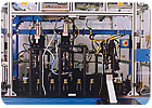
In leak testing, the choice between various methods is often driven by a compromise between cost and performance.
Hardware and Software
There is no one-size-fits-all testing solution. A low-cost, off-the-shelf test instrument rarely achieves gauge R&R in acceptable ranges, because the sensors and software are not well-matched to the application requirements.In most cases, custom software for test-intensive assemblies is actually less expensive than generic software, because it is designed to meet real needs and does not encumber users with the costs for features that are not actually required.
Moreover, generic software is not especially easy to use and does not reflect the actual data-handling requirements of the application. For example, most test applications require software that works in real-time, which is usually not the case with off-the-shelf packages. Slower, less detailed applications do not process data quickly enough to provide meaningful test control and calibration. If data analysis requirements are more complicated than generating a simple line graph, off-the-shelf software packages fall short. The best-in-class custom software will also automatically calculate R&R percentages based on the number of trials performed.
Engineers also need to think about the network their assembly and test system is running on. In a test-intensive assembly process, a lot of data is processed, so BUS compatibilities must be considered. Test-centric assembly systems will have Ethernet capability to allow huge data sets to be distributed to plantwide networks for analysis. Internet-based remote diagnostics are another feature of test-centric assembly systems.
Development of custom software for test-centric assembly starts with identifying how the data gathered during testing will be used, not just in initial production but through the entire life cycle of the product. This can be crucial for assisting with product recalls and reducing time-to-market when developing new products.
The improvements to be expected from a test-centric assembly approach are not trivial. In the best-in-class examples, cycle times for leak tests and functional tests can be decreased 25 percent to 70 percent, and yields can be increased proportionally.
A test-centric assembly approach will save money in many ways. Such systems will produce a greater return from higher yields. Value will not be added to assemblies that will ultimately be deemed defective. Faulty assemblies will not be misclassified as “good” parts, so returns are minimized. Finally, time-to-market for new products can be decreased by as much as 10 percent by mining data from assembly and test operations.
For reprints of this article, please contact Cindy Williams at williamsc@bnpmedia.com or 610-436-4220 ext. 8516.
