Assembling one part to another usually requires a third material-screws, rivets, adhesive or filler metal-but it doesn’t have to. In fact, sometimes all you have to do is bend, fold or deform a feature on one part to capture the other.
As long as one of the parts is made of a malleable material-typically metal-engineers can use a pneumatic, hydraulic or electromechanical press to crimp, stake, swage or clinch it to retain the other part. For added strength, the second part can include a ridge, groove or other feature to retain the material that flows from the first part.
Crimping involves pinching or compressing material around another part. This technique is used to attach terminals to battery cables and fittings to automotive hoses. Crimping is used to assemble solenoids, door locks, sprinkler heads and catheters.
In staking, downward pressure is applied to the end of a post or shaft, creating a head, or to the inside wall of a bore, forming one or more retaining points. The cover of a window lifter motor assembly is staked, as are the guide rings on timing belt pulleys. Bearings are often staked to shafts or bores to supplement the interference fit, and the ends of bolts are sometimes staked to prevent them from loosening.
In swaging and flaring, material from a post or cylinder is moved outward or inward radially to capture an edge or rim. Swaging is used to attach brass pins to circuit boards. It’s also used on seat belt retractors, antilock brake system cartridges and swivel joints. It’s even used on stents for cardiovascular procedures.
In clinching, a punch and die are used to plastically form a mechanical interlock between metal sheets. This technique is used on air bag housings, disk brakes, computer chassis and washing machine cabinets.
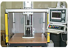
This fixture verifies that all the components of a steering column lock are present and assembled correctly. If everything checks out, a hydropneumatic press stakes five points to secure the cover plate on the assembly. Photo courtesy Schmidt Technology
Much at Stake
When designing a staked assembly, engineers should start with the strength requirements for the joint, just as they would when designing a bonded or bolted joint, says David J. Zabrosky, North American sales manager forSchmidt Technology. By knowing how strong the joint has to be, engineers can determine how many points must be staked and how much material must be moved. That information, in turn, influences the shape of the tooling and how much force is required to stake the assembly.“If you’re staking a bushing, for example, how much retention is needed? What’s the push-out or pull-out force?” says Zabrosky. “Determine those variables and then, as early as possible, start working with a good press manufacturer. Based on our experience, we can point out where problems might occur. Perhaps if you changed the tooling design, you could use less force, which saves on the cost of the press.”
The tooling for staking is made of heat-treated steel, which can be coated or uncoated. The shape of the tool is simple. For example, the tool for staking a pinion shaft is shaped like a chisel. To stake a bearing inside a bore, the tool will be slightly less than the diameter of the bore. Teeth extending radially from the tool are designed to push material down from the sides of the bore to hold the bearing in place.
“Sometimes, the tooling will be more complex, if the [assembly] has some funny geometry, but even then, the part that’s actually doing the staking is just a hardened little detail,” says Glenn Nausley, vice president and general manager ofPromess Inc.
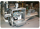
For example, Promess recently supplied a system to stake two bearing cups on a universal joint. The unassembled U-joint has a floating spider mechanism that may shift during the process of inserting and staking the cups. A method had to be found to maintain the spider in the center of the U-joint after both bearing cups have been inserted.
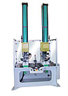
Promess attacked the spider from both sides at the same time. By using two electromechanical presses, the cups can be inserted and the spider can be centered before staking takes place. External feedback sensors locate the center of the joint. Then, both presses simultaneously stake the cups in place. By working together at the same time and speed, the presses apply equal force to both sides of the spider mechanism, ensuring it stays centered within the joint.
The key parameters for the process vary, says Zabrosky. For a staking application employing a manually operated toggle press, just knowing the ram has reached a certain position may be enough. In most cases, however, engineers want to know a certain amount of force has been applied to the part. For critical applications, engineers will want to monitor every aspect of the operation, measuring both force and displacement to ensure the right amount of force was applied in the right spots at the right time.
Unfortunately, there are no rules of thumb for setting up the press. The process usually requires some experimentation. “We recently made a customer a development tool, and he runs 15 to 20 parts, tests them, and tweaks his process,” says Zabrosky. “He’s been at it for more than three months now, but when the part goes to production, his process will be well-defined. It takes time, but it pays huge dividends down the line.”
Nausley warns engineers not to be fooled by the apparent simplicity of the staking process. “If you treat it as a primitive process, the quality is not going to be there,” he says. “You need equipment that allows you to monitor and control the process.”
Clinching produces a round, button-type connection between two to four layers of sheet metal. Photo courtesy Tox-Pressotechnik
Dramatic Flare
A classic application for swaging is a ball joint. The ball is inserted into the socket, and a press swages over the edge of the socket to create a lip that holds the ball in place.Unlike staking, which is performed with a simple up and down movement, swaging often includes a rotational component. The tooling moves around the edge as the press applies downward force.
Press control is critical. “You have to let metal flow at its own rate,” Nausley explains. “If you push it too fast, you can work-harden it, and it will be become brittle and crack.”
How much control is evident in a recent system supplied by Schmidt Technology to assemble a ball joint for a hydraulic piston pump used in a flight-control actuator. The assembly consists of two components: a swivel shoe and a cylindrical piston about 1.25 inches long and 0.25 inch in diameter. The shoe had to be swaged to the outside sphere of the piston without visible creases, and the joint could have no more than 0.002 inch of linear play.
Previously, the manufacturer used a hand-operated press to perform the swaging operation. The assembly then required a secondary roll-form operation. The process yielded inconsistent results and a high scrap rate.
To solve the problem, Schmidt supplied a servo press with closed-loop force and position control. The system automatically compensates for variation in component tolerances and compression or relaxation of the parts, tooling and press frame.
The tooling consists of upper and lower segments. Once the spring-loaded sleeve of the upper tool contacts the lower tool, the lower tool closes to a continuous circle. At that point, the piston is pressed into the socket.
This fixture verifies that all the components of a steering column lock are present and assembled correctly. If everything checks out, a hydropneumatic press stakes five points to secure the cover plate on the assembly. Photo courtesy Schmidt Technology
In a Clinch
Clinching produces a round, button-type connection between two to four layers of sheet metal. The process can join metal sheets of different thicknesses or materials. The process can even be used on stainless steel, says Bruno Maczynski, engineering manager forTox-Pressotechnik.Clinching will not damage anticorrosive coatings on the metal, and an adhesive or other material can be located between the sheets. The minimum thickness for any one sheet in the assembly is 0.1 millimeter, and the entire stack can be up to 12 millimeters thick.
The tools consist of a punch and a die. There are two types of dies: solid, fixed-cavity dies, and dies with moving components. The punch forces the layers of sheet metal into the die cavity. The pressure exerted by the press forces the punch-side metal to spread outwards within the die-side metal. Joints can range from 1.5 to 26 millimeters in diameter.
Tox has recently introduced a number of variations in the process. The Twinpoint tool creates two round joints side by side. This doubles the strength of the joint and prevents rotation of the two layers against each other.
The Vario Joint tool is for joining metal sheets with large differences in thickness; joining high-strength or nonductile materials with ductile materials; or joining metallic and nonmetallic materials. In this variation, a hole is prepunched in the bottom sheet, and the ductile material is then pushed through the hole.
In the ClinchRivet variation, a cylindrical rivet is added to the joint. “The rivet fills the cavity on the one side,” explains Maczynski. “It also increases the shear strength and pull strength. Without the rivet, if you pull the sheets apart, the material can start to collapse [inward into the hole left by the punch]. With the rivet in place, there’s no room for the material to move.”
ASSEMBLY ONLINE
For more information on assembly presses, visit www.assemblymag.com to read these articles:


