
To achieve peak output, every process and component must be selected and optimized like the parts of a high-performance race car. It’s the sum of the parts that makes a winning machine. The collective outcome of innumerable small advantages makes the difference between winning and losing.
In automated assembly, pneumatic grippers are often overlooked as candidates for upgrade and improvement. Just as the tires of a race car are important because they contact the racetrack, grippers are important because they contact the parts. However, unlike the tires of a race car, grippers don’t have the advantage of an expert constantly monitoring and controlling their performance.
Too often, grippers operate blindly without any feedback regarding their status or condition. These “dumb” grippers don’t give the host controller any information about whether they opened or closed, how far they opened or closed, or whether they successfully grabbed a part. As a result, processes can fail when the actual gripper status differs from the expected condition.
Fortunately, various sensor technologies can give dumb grippers the feedback necessary to become smart. The optimum sensor technology to choose depends on what parameter of gripper performance needs to be monitored.
Three gripper parameters are most commonly monitored:
* Jaw open, jaw closed, jaw closed on part.
* Actual jaw position.
* Part present or absent in gripper jaw.
An analog inductive proximity sensor continually tracks the position of the jaws by reading the distance of the wedge face from the face of the sensor.
Jaw Open, Jaw Closed
The most basic form of gripper status monitoring is to check whether the jaws are open or closed, and whether they closed on a part. Discrete on-off signals from sensors confirm that the gripper is mechanically executing control commands as expected. Failure to confirm gripper status could result in line stoppage and damage to work-in-process and production equipment. Reliable gripper status signals can detect gripper faults when they occur, allowing automatic, orderly stopping of the process so that problems can be corrected before scrap is produced or machinery is damaged.
For grippers operated by linear-acting prime movers, such as pneumatic cylinders, there are two primary approaches to determine if the jaw is open or closed. The direct approach is to monitor the jaws themselves. The indirect approach is to monitor the mechanism that moves the jaws.
For the indirect approach, magnetic field sensors are used. The sensors monitor the position of the actuator that moves the jaws, giving an indirect indication of whether the jaws are open or closed. Two magnetic field sensors installed on the exterior of the built-in pneumatic cylinder of the gripper give jaw position. The piston inside the aluminum-walled cylinder has a magnetic ring around its circumference. The sensors detect the presence of the magnetic ring as it moves past them, causing them to change their outputs from low to high. The sensors are typically mounted in extruded slots on the outside of the cylinder, so they can be precisely positioned along the axis of motion to set the exact switch point.
Normally, two or even three sensors can be installed to indicate that:
* the jaws are fully open.
* the jaws are fully closed.
* the jaws closed on a part.
Very small magnetic field sensors are available for installation in tight spaces or where the piston stroke is 0.5 inch or less.
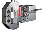
For the direct approach, miniature inductive proximity sensors are used. The sensors detect the metal of the jaws themselves, or metal targets attached to the jaws, such as screw heads or brackets. This technique is useful when the indirect method cannot be employed, such as when the piston does not have a magnetic ring or when the cylinder walls are made from ferromagnetic steel instead of aluminum or nonmagnetic stainless steel.
Miniaturization of inductive proximity sensors allows them to be successfully applied to today’s increasingly small grippers. Inductive proximity sensors are available with diameters as small as 3 millimeters and lengths as short as 6 millimeters. These devices are fully integrated and do not require bulky external amplifiers.
* the jaws are fully open.
* the jaws are fully closed.
* the jaws closed on a part.
Very small magnetic field sensors are available for installation in tight spaces or where the piston stroke is 0.5 inch or less.
For the direct approach, miniature inductive proximity sensors are used. The sensors detect the metal of the jaws themselves, or metal targets attached to the jaws, such as screw heads or brackets. This technique is useful when the indirect method cannot be employed, such as when the piston does not have a magnetic ring or when the cylinder walls are made from ferromagnetic steel instead of aluminum or nonmagnetic stainless steel.
Miniaturization of inductive proximity sensors allows them to be successfully applied to today’s increasingly small grippers. Inductive proximity sensors are available with diameters as small as 3 millimeters and lengths as short as 6 millimeters. These devices are fully integrated and do not require bulky external amplifiers.
A magnetoinductive sensor tracks the position of an internally installed magnet to provide constant position information.
Actual Jaw Position
Absolute analog position measurement of gripper jaws can deliver precise feedback signals to increase assembly speed, improve quality control and indicate the need for preventive maintenance. Analog signals can be used to create multiple set points in the control software for programmable, flexible production systems. These signals can also be used to differentiate between fully gripped objects of different sizes. And for soft or deformable items, the amount of applied gripper pressure can be dynamically adjusted to produce just the right degree of squeeze on the product to ensure a secure grip without marking or damaging the item.Analog signals can also be used to monitor the operating efficiency of the gripper mechanism. For example, if there is a leak in the air line or a failing jaw mechanism, the gripper will operate more slowly. This abnormally slow motion can be detected by analyzing the rise and fall time of the real-time analog signal in the control software. Preventive maintenance messages can be generated to alert personnel to service the gripper at the earliest convenient opportunity, to stop a pending failure before it stops the line.
For grippers driven by linear-acting prime movers, there are again two approaches to determine the actual, or analog, position of the jaw: direct and indirect.
For the direct approach, an analog inductive proximity sensor can be configured to directly sense the linear motion of the jaws. The sensor outputs an absolute analog position signal that is directly proportional to the motion of the jaws.
Alternatively, the gripper jaw is fitted with an angled or sloping metal target that moves with the jaw. The sensor provides a high-resolution voltage or current output that is directly proportional to the target distance from the sensor, and thus its signal is directly proportional to absolute jaw position.
The sloping metal target is used to translate a 1- or 2-inch jaw motion into a smaller target displacement that is within the relatively short sensing range (typically 1 or 2 millimeters) of the analog inductive sensor. Because the sensor is an absolute rather than incremental device, after a power interruption the analog inductive sensor turns on and supplies the correct actual jaw position signal without any need for homing the gripper jaws, which might be inconvenient if a part is already held in the jaws.
For the indirect approach, an analog magnetoinductive linear position sensor is used. Instead of discrete magnetic field sensors, an analog magnetoinductive linear position sensor is fitted to the gripper cylinder housing to continuously sense the internal magnet mounted on the piston. Rather than on-off position signals, the sensor outputs an absolute analog position signal, such as 4 to 20 milliamps or 0 to 10 volts, that is fed back to the control system.
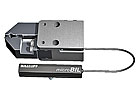
A flat pack inductive proximity sensor verifies that a part is in the jaws.
Part Present or Absent
Detecting the presence or absence of a part in a gripper jaw can provide key information about the status of an assembly process. If a gripper expects to pick up a part and no part is detected, it could mean that the gripper is starved for parts by a stoppage farther up the line. It also might mean that the end of the production lot has been reached and the process is ready to be shut down.In some cases, multiple grippers must simultaneously grab a large or heavy part. If one or more grippers fail to grip the part, the “lift and move” operation could fail, dropping or dragging the part, causing damage to the part and the surrounding equipment. Moreover, the time spent clearing the subsequent jam could incidentally harm work-in-process farther up the line-if, for example, parts remain too long in an oven or chemical bath.
There are two convenient and reliable sensor technologies for detecting parts in grippers:
* Inductive proximity sensors.
* Self-contained photoelectric through-beam sensors.
If the part is metallic, such as sheet metal, machined parts or castings, inductive proximity sensors can be integrated into the gripper jaws to directly sense the metal part. Sensors used in this manner are typically low-profile block style housings commonly called “flat packs.” The flat pack housings can be plastic or metal, but in any case, the sensor must be high-quality and designed to withstand repeated shock and vibration. The sensor cable should also be designed for continuous flexing without internal conductor fatigue and breakage.
Self-contained through-beam photoelectric sensors can detect part presence regardless of material. Certain versions can even detect clear glass or plastic. Various light sources can be employed depending on the characteristics of the part, the operating environment (clean or dirty), and how precisely the part must be positioned in the gripper. Light sources include infrared, visible red or visible red laser.
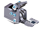
Self-contained through-beam sensors are available in U-slot or L-style configurations. U-slot types require the part to be introduced from one direction, while L-style sensors can accept part introduction and removal from multiple directions. Available in a variety of sizes, through-beam sensors can be fitted to virtually any size or style of gripper.

An L-shaped photoelectric sensor confirms that a part is present in the jaws.
Selecting Sensors
When selecting sensors for gripper applications, some key points to consider include wear, temperature stability, environmental ratings, connection style and light source.Electromechanical limit switches are prone to mechanical failure and contamination of their electrical contacts. Magnetically actuated reed switches are prone to contact sticking and welding. When applying sensors to grippers, it’s important not to introduce additional failure modes into the process. Unreliable sensors can be as bad as no sensors at all, and can derail your smart gripper initiative. Wear-free, solid-state sensor technologies, such as magnetoresistive, inductive, magnetoinductive, capacitive and photo-electric, are the best option.
Look for sensors that maintain stable sensing characteristics despite changes in temperature within their operational range. Sensors whose switch-points or signals drift with temperature can create setup and adjustment headaches.
Select sensors with enclosure protection and temperature ratings that meet or exceed the demands of the production environment. For example, don’t install standard-temperature sensors into extremely hot applications or wash-down environments. Be sure to seek sensors specifically designed and specified for such extreme conditions.
Sometimes, it’s a matter of preference, but in general, use sensors with quick-disconnects. This allows faster sensor replacement if necessary and enables easy change-out of entire grippers with sensors already preinstalled and adjusted. Just disconnect the sensors and remove the entire gripper assembly, sensors included.
Infrared is the light source of choice for dirty, dusty conditions. Infrared light has enough power to burn through accumulated dirt and grime and keep on working. Visible red light is useful where it’s important for human operators to see the beam spot with the naked eye. Visible red laser light is selected where the part features being detected are very small or precise. For example, if a part contains numerous perforated holes, it is necessary to align the narrow laser light beam so that it is broken by a solid area and doesn’t pass through any of the holes to the receiver.
Today’s advanced sensors can add an entirely new level of flexibility and performance to robotic grippers. Once installed, they will lower unplanned downtime, and raise the productivity and profitability of your entire operation.