
Round and round and a quarter-round coiled pins go. And where they’ll be used, only assemblers know.
These pins are part of the family of nonthreaded tension fasteners, which also includes slotted, hollow and various solid pins and studs. Hundreds of millions of coiled pins are used annually in the assembly of many products, especially cosmetic cases.
“The coiled pin is the fastener of choice for many assemblies because it is strong enough to resist the working loads of the assembly, yet it can also flex indefinitely both before and after insertion,” says Christie L. Jones, market development manager at SPIROL International Corp. “This flexibility helps the pin stay in the hole, especially for hinge applications and those involving extensive vibration.”
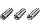
The pins are
available in three material thicknesses: light, medium and heavy duty. Photo
courtesy Driv-Lok.
Why Invented
Coiled pins were invented by Herman Koehl and brought to market in 1948. A German scientist, Koehl immigrated to America during World War II. He worked for the U.S. Air Force, which was having trouble keeping lighter-weight turbines for airplane engines fastened together. The Air Force tried using nuts and bolts and other press-fit pins such as solid pins, but extensive vibration made them loosen and fall out.Koehl solved the problem with coiled pins. The pins stayed in place because they were strong enough to resist the engine’s vibration force but flexible enough to absorb the dynamic load rather than transmitting the force to the hole wall.
“When a load is applied, something has to give: the pin, the hole or an element of the assembly,” says Jones. “A pin that is too rigid causes the hole in which it is retained to elongate. This leads to eventual assembly failure. However, a pin that is too flexible could result in pin failure by fatigue under dynamic loading.”
Where Used
Coiled pins are used extensively in cosmetic cases, automotive door handles and locks, and latches as hinge pins. They’re also used as pivots and axles, for alignment and stopping, to fasten multiple components together-such as a gear and shaft-and even as ejector pins to remove motherboards from PCs. The automotive and electrical industries use coiled pins in such products as steering boxes and columns, pumps, electric motors and circuit breakers.
“Coiled pins hold aesthetic materials on the triggers of guns and rifles,” says Dale P. Stuban, vice president and general manager of Vogelsang Corp.
“Coiled pins are used in aluminum blocks and castings to help them better withstand insertion force,” adds Mike Apsey, product development engineer for Driv-Lok.
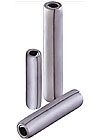
The coiled pin’s outer diameter ranges from 1/32 to 3/4
inch, and its standard length is usually no more than 6 inches. Custom lengths
and features also are available. Photo courtesy Vogelsang Corp.
Features and Benefits
The coiled pin consists of a 2-1/4 helical wrap of carbon, stainless or alloy steel. Its outer diameter ranges from 1/32 to 3/4 inch, and its standard length is usually no more than 6 inches. The pin’s outer diameter is slightly larger than the hole diameter to ensure snugness. When correctly sized and installed, the pin offers a minimum of 270 degrees of radial contact in the hole.“This increased contact improves load distribution and decreases the possibility of hole damage-especially when the hole is close to the edge, or in soft or thin material,” says Stuban.
Coiled pins also offer lower hole preparation costs than other fasteners because holes only have to be drilled rather than drilled and reamed. Plus, unlike other nonthreaded fasteners, secondary operations are not required to retain coiled pins. In contrast, rivets, for example, require the operator to upset the end of the component for retention. A final benefit is reusability. When driven from a hole, the pin expands to its original diameter and can be reused.
The pins are available in three material thicknesses, which let the design engineer optimize the pin’s strength and flexibility for a specific application. Light-duty pins are generally recommended for soft or brittle materials. Medium (or standard) duty pins are recommended for use in mild steel and nonferrous assemblies. Heavy-duty pins should be used in hardened components. All pins are manufactured in accordance with several standards, including ASME B18.8.2-2000, ASME B18.8.3M (metric), ISO 8748, ISO 8750, ISO 8751, and the military standards NASM 10971, NASM 39086, NASM 51923, NASM 51987, NAS 561 and NAS 1407.
Specialty coiled pins include those with a stud-like head, flared top, reduced ends, extra-flexible outer coil and extra-smooth outer coil that inserts flush inside the hole surface. Also available is a 1-1/2-coil construction, extra light-duty pin for fragile materials. Suppliers can also custom-design coiled pins to best match a manufacturer’s application.
Available finishes include zinc plating, phosphate and oil, black oxide and passivation. In addition, all coiled pins are oiled to decrease the coefficient of friction between the coils and increase the pin’s flexibility.
Coiled pins manufactured from stainless steel and other corrosion-resistant material can be supplied oil free if used in medical devices or if the oil is not compatible with the host material, such as certain ABS plastics.

Coil pins can be
installed manually with a hammer or arbor press. The fasteners can be installed
manually in approximately 3 seconds per pin. Photo courtesy SPIROL
International Corp.
Installation and Performance
Coiled pins can be installed manually with a hammer or arbor press, or automatically by a vibratory feeder with an insertion device. The fasteners can be installed manually in approximately 3 seconds per pin.Once a coiled pin is installed, compression begins at the outer edge and moves uniformly through the coils toward the center. When a load is applied to the pin, it continues to flex. Stresses are distributed equally throughout the cross-section, and shock and vibration are absorbed. Pin strength is not affected by the direction of the applied load.
According to suppliers, the most important thing assemblers must do when installing coiled pins is make sure all five of the coil edges are forced into the hole. Placing force only on the inner two or three coil edges will make the pin telescope.
Assemblers also need to make sure radial force is exerted by the pin to the end of the hole. They can accomplish this by letting the pin protrude approximately one-fourth of its nominal diameter, which is the approximate length of the chamfer.
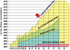
Coiled spring pins have a
greater total hole tolerance than other types of nonthreaded tension fasteners.
Courtesy of SPIROL International Corp.
Selection Factors
To select the right coiled pin for a specific assembly, a manufacturer should consider many factors, including:Familiarity with pin fasteners. Despite coiled pins’ long history and frequent use, many assemblers know much more about how screws, nuts and bolts perform. Assemblers need to become informed about coiled pins. “Make sure coiled pins are right for the application,” says John Miller, R&D manager for Driv-Lok.
Host material. Is the material very strong, very brittle or something in between? This information will help the assembler decide if a light-, medium- or heavy-duty pin is best. In addition, suppliers can control how tightly the pin’s steel is wrapped to accommodate the host material.
Sheer and load.Testing and statistical analysis must be performed to obtain this specific data. “Otherwise, the assembler may learn down the road that a solid pin should have been used rather than a coiled pin,” says Gary Seegers, president of Drive-Lok.
Hole quality.Jones says the edges of hardened holes should be deburred, and excessive burrs from drilling or stamping holes should be avoided. Also, cast or sintered metal holes should be provided with a slight lead-in radius.
Shaft design. Frequently, coiled pins must be driven into shafts that drive gears and other mechanisms. The hole drilled into the shaft for the coiled pin should not exceed one-third of the shaft diameter.
Temperature. Temperatures more than 300 F and lower than -50 F should be avoided with carbon and alloy steel pins. Some stainless steel pins perform best in temperatures from 500 F to -300 F; others in temperatures from 700 F to -50 F.
