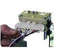
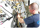
When a connector pin is inserted correctly, the easy-wire system provides specific visual cues. Because the furthest left wire is inserted correctly, the LED lights up green. If the wire was not in the correct position, the LED would blink red.
A guided harness assembly and test system makes sure that assemblers insert wires correctly by giving them instant feedback. Cirris Systems Corp., a long-time supplier of cable and harness test equipment, offers such a system, which is called easy-wire.
To assemble a wire harness, wires are first cut to length, identified (markings, labels or color), terminated with pins or contacts (crimped, soldered or welded), and inserted into connectors. Sometimes all wires are inserted into connectors. In other cases, they’re not. These wires might be terminated with ring lugs, spades or even left bare for termination at the point of final use. In any case, the completed harness must be electrically tested to verify proper wiring before being delivered to the customer.
If wiring errors are not discovered until the completed harness is tested, it must be sent back to the assembly area for repair and rework, or it must be reworked while still plugged into the tester. This can create a bottleneck at the test station, tying up expensive test equipment.
The goal of the easy-wire system is to move electrical testing of harnesses as far upstream in the assembly process as possible. If wiring errors can be detected when and where they occur, preferably by the assemblers, then quality goes up while overall cost is driven down. This also provides valuable learning opportunities for root cause analysis.
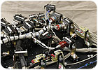
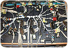
This
image illustrates how complex a harness board can be-and how daunting assembly
can be without an aid that takes all the guess work out of it.
By Any Name...
Whatever name you give the easy-wire system-guided harness assembly, test as you build, in-process verification, zero-defect assembly aid-it helps assemblers build harnesses quickly and accurately, resulting in low overall cost and high reliability.The system is a combination of hardware and software, along with optional components that help assemblers wire up the harness board for assembly and test. The system’s software can be used to control both the low-voltage CR tester and the high-voltage CH2 tester.
Harness boards that are already back-wired for testing can generally be used with little or no modification. A full line of accessories has been designed to help ergonomically set up boards for assembly. These include grid tiles, brackets, bracket bases, connector holders, LEDs and drop-nail brackets.
Equally important are grid tile assembly clips and the 3/4-inch-thick hardwood-faced plywood board, which must be purchased.
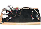
The easy-wire system comes with accessories that help an
assembler set up a harness board. These include grid tiles, brackets, bracket
bases, connector holders and nail brackets.
The tiles are joined together with the clips, placed down so they’re square to the plywood edge and screwed in place. The assembler then attaches his drawing to the grid board and makes sure the drawing is square to the board. Next, notes are made on the drawing as necessary to record the configuration of the brackets. Finally the brackets are attached to the board, and wires can be connected.
Test programs, which double as build programs, can be created within the software, imported in electronic format, or self-learned from a known good sample. These programs contain all of the information required to build and test the harness, including the “From-To” wiring list, wire colors, labels, test parameters, splice information, and component placement and values (resistors, diodes, capacitors and switches can be tested).
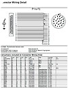
An
assembler can create reports that provide a visual representation of the cable
or harness he is testing. This image illustrates, in a visual way, what the
cable looks like, where the components are, and what the connectors look like
on either end of the cable.
First and Second End Pinning
Typically, harnesses are assembled using a “first end, second end” method. One end of each terminated wire is installed into a main or trunk connector. The opposite ends are then routed to myriad other connectors.Often, a point from one connector will go to two or more points somewhere else in the harness. These are usually routed though splice junctions, where the originating wire is spliced to two or more separate wires that run to their respective end points.
The assembler must locate each wire at its end-point connector and insert it into the correct cavity. If wire is labeled, the operator reads the label, looks up the corresponding cavity location on a paper lookup table, and then counts cavities to find the correct one. This can be particularly time-consuming and error-prone, especially on connectors with dozens, if not hundreds, of points. If wires are not labeled, the assembly process often requires two assemblers using an ohmmeter to “beep out” the wires, one by one, searching for the correct wire to insert next.
With the easy-wire system, the operator simply touches the end of a wire at the end-point connector and is told where that wire comes from, and where it goes to. An on-screen graphic of the connector is displayed, with the target cavity highlighted in green. On the harness board, bi-colored LEDs blink green at the from and to connectors.
If the assembler inserts the wire into the correct cavity, a “good” tone sounds, the LEDs blink green, and the software moves on to the next instruction. If the assembler inserts the wire into the wrong cavity, a “bad” tone sounds, the cavity where the wire was inserted is highlighted in red, the LEDs blink red, and the software displays the miswire information. Using this system, it is impossible for assemblers to build the harness wrong, because they simply can’t go on to the next wire until the current one is inserted correctly.

If wiring errors
can be detected when and where they occur, preferably by the assemblers, then
quality goes up while overall cost is driven down.
Random vs. Sequential Mode
On small connectors-those with less than 30 cavities-assemblers can install wires in just about any order. However, when the pin-count exceeds 60 cavities, as with circular connectors for military applications, it is desirable to insert wires from the center out (spiral pattern) or work from left-to-right or top-to-bottom (column pattern). This approach avoids “bird caging” or uneven nesting of the wires.For high pin counts, the system can be set to “sequential build” mode. In this mode, instead of touching any wire, the assembler must probe wires until the next wire in the test program sequence is found. A “ding” tone sounds when the next wire is probed, alerting the assembler that he has found the correct wire. This process actually proceeds faster than one would expect, because the assembler is working on a continually shrinking group of wires as they are assembled in the sequential order.
The goal of the
easy-wire system is to move electrical testing of harnesses as far upstream in
the assembly process as possible.
More Helpful Features
To further enhance harness assembly, this system is compatible with Microsoft’s Text-to-Speech feature. With speakers or a headset attached, the system software literally speaks the information from the monitor to the operator. This can significantly increase the speed at which the assembler works, since he doesn’t have to keep looking at the monitor for information. This feature is especially useful on long harness boards where multiple monitors might otherwise have to be placed.The system also has a “comment” feature that allows for the insertion of on-screen operator prompts anywhere in the build program. Additionally, electronic files can be attached to these comment instructions so they appear on screen at a specified time. These files can be digital photographs, Word documents or even a copy of existing printed work instructions.
Equally beneficial, the system allows for complete documentation and data collection. Schematic wiring diagrams can be displayed or printed. For statistical process control, the system tracks assembly time and logs final test results. Also, testers can be networked to allow full factory control in a single database. Test programs generated offline by engineering are available to all testers on the network.
One end of each
terminated wire is installed into a main or trunk connector. The opposite ends
are then routed to myriad other connectors.
Customer Success Stories
Since its inception, the system has been implemented in hundreds of wiring harness shops, both large and small. Here are a couple customer success stories.Raytheon’s Network Centric Systems facility in Largo, FL, first implemented our system in 2003. In a “Best Practices” survey, the company reported that typical harness build times have decreased by a factor greater than four, and regressive flow due to missed wires has been virtually eliminated. First-pass yields grew from 82 percent to 98 percent.
“All of this has yielded significant cost reductions for the company, along with increased quality,” the company wrote to us. “By not having to handle the harness assemblies to test for continuity, test times are reduced and handling-induced wire breakage is eliminated.”
Boeing Corp.’s Mesa, AZ, facility uses our system to assemble harnesses for the F/A-18 fighter jet and Apache Longbow helicopter. The company wrote: “Since the technology was introduced four months ago, the last 60 harnesses built with it had zero operator errors. The step of removing the harness and bringing it over to another test area is eliminated. The system is estimated to save the company more than two labor hours per wire harness, and save thousands of dollars in labor hours.”
