A large automotive electrical harness can contain hundreds of wires, dozens of connectors, and several electronic components, such as relays and diodes. Despite crimp-force monitoring, pull-force testing and other pre- and postassembly checks, there’s no guarantee that every crimped connection will be tight, every inch of insulation will be undamaged, and every wire will be inserted into its correct destination.
As a result, wire shops put every harness, large and small, through a battery of tests for safety, continuity and functionality.
Insulation, connections and intermittent faults can be verified using low-voltage, high-voltage and high-current tests. Basic continuity testing can range from a quick pass-fail assessment of a wire connection to a precise resistance measurement. For power cords and appliances, high-voltage testing ensures the integrity of the line, neutral and ground circuits. In other cases, high current may be needed to energize a component to ensure it works correctly.
Test equipment can be standalone, microprocessor-based systems, or they can be PC-based. In the latter case, the PC can be external to the tester or embedded in it.
Microprocessor-based systems are robust and simple, says Rafael Astorga, sales engineer for Dynalab Test Systems Inc. “If you look at the interface [for the NX tester], it’s a four-button display,” he says. “It’s very user-friendly.”
PC-based systems offer the advantages of flexibility, better graphics, and the ability to perform complex testing routines. “The advantage of a PC-based system is that we’re constantly upgrading our software,” says Christopher E. Strangio, president of CAMI Research Inc. “The tester never becomes obsolete.”
Modular switching units can be distributed around the unit under test, thus eliminating long, cumbersome adapter cables. Photo courtesy DIT-MCO International Corp.
PC-Based Systems
One example of a PC-based system is the Series 90 analyzer from Cablescan Inc., the test equipment subsidiary of Eubanks Engineering Co. The device can perform high-speed testing of wire harnesses, backplanes and printed circuit boards. Available in both low- and high-voltage versions, the analyzer consists of a Pentium-based controller, keyboard, VGA color monitor, and one or more expansion cabinets housing scanner boards.Each version can have up to 32 expansion cabinets, though high-voltage and low-voltage cabinets cannot be intermixed. The controller and each expansion cabinet can be separated by up to several hundred feet, for applications requiring interconnects spread over a large area, as in testing aircraft and shipboard cabling.
Test programs can be created internally using the keyboard and a specialized wire list editor, or they can be obtained externally by scanning a known-good assembly or importing CAD data, explains David Eubanks, president of Eubanks. The software enables engineers to define component values and tolerances for circuits containing resistors, capacitors and diodes. Additionally, diode and capacitor polarities can be defined, as well as diode-forward voltage drops. Continuity and isolation thresholds can be programmed at three levels: as system defaults, in individual programs, or while running specific tests.
Test programs written for one version of the Series 90 can be run on any other version simply by changing the test voltage and isolation settings.
The device can check for continuity, opens and shorts. A single test scan or continuous scans may be performed. The unit can show test results in three ways: display the value of each circuit and component tested; display only the failed circuits and components; and display just the final pass-fail status. Passwords can be programmed to control access to high-voltage testing. The device can print complete test results or just a pass-fail label.
Test results may be serialized and stored for use in generating test summary reports. Build times may also be saved for use in creating reports comparing assembly times against standards.
The device can do more than just test wire harnesses. It can also help operators to assemble them. The device relies on body conductance to help operators locate and identify assembly points by touch. Audio as well as visual outputs indicate when the correct point is touched.
During assembly, the Series 90 verifies each circuit as it is terminated. It can operate in a predetermined build sequence or allow terminations at random. The build method can be programmed to switch automatically between sequential and random. The wire list may also be grouped to allow a section to be routed without terminating. Once the section is routed, the Series 90 verifies each circuit as it is terminated.
Color graphics and text displays provide detailed work instructions. This enables a “paperless factory” environment, providing automatic indexing to the corresponding assembly details for each circuit.
The Series 90 can be set to retest the previously terminated circuit for continuity. If that circuit becomes unterminated, the device automatically backs up, allowing retermination. This feature prevents the tester from permanently advancing and displaying the next circuit while the immediate circuit makes only temporary contact with the terminating point. Connector pins that back out after the operator releases the wire will also cause the tester to back up.
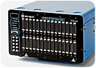
The controller for the Model 2650 wiring analyzer is available as a portable module supporting up to 15,000 test points or in a cabinet supporting larger systems and incorporating rack-mounted accessories. Photo courtesy DIT-MCO International Corp.
Going Modular
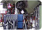
Modular test equipment can be an advantage when testing long, complex harnesses for airplanes, boats and other large products. One example is the Model 2650 from DIT-MCO International. The system’s modular switching units can rack-and-stack in a cabinet to provide concentrated test points, or they can be distributed around the unit under test (UUT), thus eliminating long, cumbersome adapter cables. Engineers can reconfigure the system at any time when needs change.To provide efficient test operations with large UUTs, moving the tester close to the product under test is optimal, says Barry Kendrick, Midwest regional sales manager for DIT-MCO. The distributed configuration eliminates unwieldy adapter cables that are expensive to rework and difficult to store.
The switch modules can be placed remotely where needed, such as a cockpit or wing section, or they can be stacked on a trolley for mobility and flexibility. Engineers can also mix racked modules with distributed modules.
Each switching module supports up to 1,500 test points per unit. The module can be configured to suit specific needs in increments of 100 points. Test interfaces on the standard unit are either 150-point ZIF or 50-pin D-sub connectors. Small, lightweight, 500-point modules are available for locations where only a few test points are required.
External energization and test probe connections are built into each module, so engineers can quickly access any point that requires power or testing with the probe. If a large number of external energization points are needed, special dedicated switching modules are available.
With the Model 2650’s optional random hookup feature, engineers can attach adapter cables in any order. A bar code or embedded identification tag identifies the cables and their locations. The test system automatically matches the cable hookup and runs the test program.
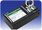
The Easy Touch harness tester checks for opens, shorts and miswires. It also performs insulation resistance and dielectric withstand testing. It has an integrated PC complete with hard drive, and ports for VGA, USB, Ethernet and audio. Photo courtesy Cirris Systems Corp.
Making Connections
Suppliers have also found ways to simplify the process of connecting wire harnesses to testing equipment.For example, the EasyMate connector system from DIT-MCO uses modular blocks so engineers can match the test system interface to the unit under test. Instead of complex, custom-made branched cables, engineers can connect the harness to the tester using simple, one-to-one, interface cables that can easily be used on multiple units.
The test interface module contains 500 contacts and has a metal body that resists damage. Plugs range from 10 to 100 pins. They can be inserted quickly with one downward motion and a low insertion force. A latch retains the connection during testing.
Contacts are plated with 25 microns of gold over copper to provide a reliable electrical contact with low resistance. Insertion of the connector creates a wiping action resulting in a low-current-capable connection.
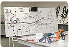
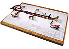
Wire shops put every harness, large and small, through a battery of tests for safety, continuity and functionality. Photo courtesy Painless Performance Products LLC
ASSEMBLY ONLINE
For more information on wire harness testing, visit www.assemblymag.com to read these articles:•Wire Processing: Guided Harness Assembly and Testing.
•Assembly in Action: Marine Analyzer Tests Uncharted Wa-ters.
•Assembly in Action: Tester Boost Production.
