
These days, designing a robotic system to assemble parts or load and unload machines is no big deal, even for the most challenging factory environments. If, however, the robot will be performing those tasks on the moon, that’s a whole other ballgame.
With the retirement of the space shuttle program, NASA is once again turning its attention to the moon, this time with the goal of establishing a permanent base on the lunar surface. Crucial to that effort will be robots that can unload lunar landers, assemble prefabricated base components, and manipulate tools and scientific instruments.
One of the agency’s prototypes for such a mission is the Lunar Surface Manipulation System (LSMS). Designed by engineers at NASA’s Langley Research Center, the robot is similar to a crane, but with more dexterity. The system is designed to work remotely, so it can be used on unmanned missions without human interaction. It’s completely autonomous.
Given the robot’s multitasking mandate, the LSMS was going to need a robust mechanical tool changer, and NASA contracted with Honeybee Robotics Spacecraft Mechanisms Corp. to develop it. Honeybee has been developing harsh-environment, mission-critical end-effectors for more than 25 years, so it was particularly suited to the challenge.
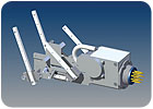
The male connector is cylindrical and populated with 11 aluminum pins plated with gold over nickel. Photo courtesy NB Corp.
Making It Work
NASA provided Honeybee with a footprint for the end-effector, as well as load ratings, misalignment allowances and other specifications. The rest was up to Honeybee.“The crane might be sitting on the lander deck or on the lunar surface and would be driven from quite a distance away from the tool to be mated to,” says Lee Carlson, a systems engineer at Honeybee. “This required designing for large misalignment allowances. …The end of the crane and target tool could be misaligned by as much as a couple inches in any direction with up to 20 degrees of angular misalignment when attempting a mate.”
There were other design challenges, too. “The tool changer had to be capable of carrying 1,000 pounds, so it had to be very robust,” says Carlson. “Also, since this was a lunar project, it had to be tolerant to moon dust. These two design criteria [meant that we would need] special seals to protect large roller bearings. If this design was for space, it becomes considerably simpler. All of the loads would be reduced, and dust is no longer an issue. But the moon is a very harsh environment, and lunar dust is a major concern when designing for missions there.”
The original assignment called for unpowered tools. The crane would do all the work. Tools included a forklift attachment, a shovel for digging or acquiring surface samples, and a bucket for lifting human passengers.
Then, NASA decided it wanted the capability of attaching electronic or electromechanical tools to the end of the crane. Now, the tool changer would have to provide an electrical connection, as well. Solving this problem fell to Carlson.
“The contract was expanded to add an electrical connector to the existing mechanical connector,” he recalls. “You’d have a power source on the LSMS itself, so your tools could be powered. That way, your tool capabilities could expand into the realm of cameras, or tools with cameras on them, or even a light jackhammer.”
However, the Honeybee design team had not left space to accommodate an electrical connector, since it was not a part of the original contract. Worse, the budget did not allow for redesigning the end-effector from scratch.
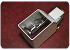
Honeybee engineers had roughly 2.5 by 4 inches of free space to incorporate the male side of the connector. Photo courtesy NB Corp.
The Crucial 10 Square Inches
Carlson had to work within the constraints of the current design. He had roughly 2.5 by 4 inches of free space to incorporate the male side of the new connector, which would mate with a female side mounted on the tool. “We make small stuff all the time, and if there were more space, there are many different ways that I could have designed it,” says Carlson. “This is, probably, the most compact I’ve ever had to make anything.”Honeybee designed both the male and female sides of the connector. The female side had to be inexpensive and easy to create, since each tool would need its own connector.
In Carlson’s design, the female connector has no moving parts and is slightly compliant. The male connector has all the moving parts. It is cylindrical and populated with 11 aluminum pins plated with gold over nickel. The pins are 0.0625 inch in diameter and configured in a standard MIL-spec pattern.
The male connector rides on compact linear slides-miniature SEB guides made by NB Corp.
“We used a total of six slides within the space-three on each side,” says Carlson. “The slides ride on each other in the manner of drawer slides that are stacked to extend the distance they can open a drawer. Our configuration achieves an extension of the movement equal, approximately, to the length of three slides. So instead of a 0.5-inch stroke, we could get a 1.5-inch stroke within a very small footprint. Low mass, low load and very low profile were all required for this application.”
The top sides of the slides face each other, with the connector assembly mounted in between. This configuration reduces moment loads on the slides.
Carlson chose the SEB guides because they were among the smallest he could find. His one caveat was that he wanted to work with a supplier that Honeybee had used before; he did not want to take chances with a new supplier. Even though the slide was for a prototype, it still had to be made completely of stainless steel, without any plastics. (Plastics are generally avoided in space applications.) To protect against lunar dust, the entire connector assembly would be sealed in a bellows.
The major advantage of the SEB guides is their tight radial clearance. Most manufacturers do not claim that their preload eliminates all clearance. Their standard guides are rated plus to minus, which allows for some clearance. A minus rating means there is some preload, but there’s no gap.
NB’s guides are rated from zero to minus as a standard, making for greater accuracy, because there is no clearance. In other words, a negative clearance means the ball is larger than the space, adding more pressure and greater rigidity. This increased rigidity is desirable in high-precision applications.
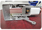
The male connector rides on six compact linear slides, three on each side. Photo courtesy NB Corp.
Other Options
Of course there can be instances in which no preload is desired. Engineers may want to trade off accuracy and rigidity for minimal friction. In such a case, engineers might want clearance. But the space mission was not such a case.Had Honeybee taken a different design route, engineers might have had to worry about deformation of the guide block. For instance, had the connector been mounted on only one rail on an arm that extended to the side, this could have caused deformation of the block, reducing accuracy.
There is a linear guide for this problem, too. It’s called the SEB-AD. The AD version is stiffer because NB optimizes the machining of the top-mounting surface of the guide block that attaches to the table. This withstands the extra moment load that could have caused some clearance due to deformation.
For the smallest applications, NB offers an extra-compact block for slight loads, the SEB-BS, which is shorter than the standard length block and has only two holes instead of four. The SEB-BS is available in both retained-ball and non-retained-ball versions. The former allows for easier handling, since the guide block may be removed from the rail without losing the balls.
If greater rigidity is required, the SER linear guide should be considered. It has crossed-roller bearings, which provide greater contact area than ball bearings. Made entirely from stainless steel, the SER slide has non-retained rollers and is available in the same block sizes and configurations as the SEB guides.
In recent tests executed by Newmark Systems Inc. of Rancho Santa Margarita, CA, NB’s miniature guides have proven not to wear even after 1.5 years of constant travel.
For more information on linear guides, call NB at 800-521-2045 or visitwww.nbcorporation.com.

Crossed-roller miniature guides can carry greater loads than ball-bearing guides. Photo courtesy NB Corp.
ASSEMBLY ONLINE
For more information on motion control, visit www.assemblymag.com to read these articles:•Assembly in Action: Slides Hoping for a Ride to Mars.
•Motion Control: How to Specify Short Linear Actuators.
•XYZ: Ballscrews Provide Fast, Accurate Linear Motion.
