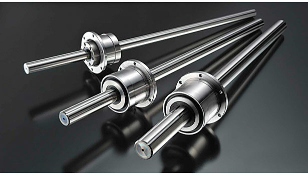
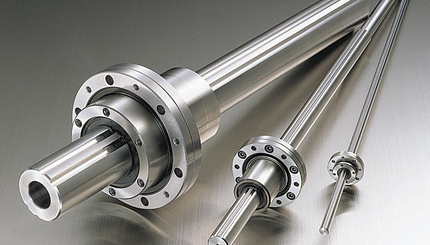
A ball spline consists of three components: a grooved shaft, a spline nut and ball bearings. The grooves on the shaft are linear rather than helical like those of a ballscrew. The balls travel along the grooves, recirculating inside the spline nut. This prevents the nut from rotating on the shaft, enabling transfer of torque through the shaft to the nut or vice versa.
In a typical application, either the shaft or the nut is mounted to a fixed structure. With a fixed shaft, the ends of the shaft can be turned down to accommodate the mounting of radial bearings to support rotation. With a fixed nut, however, the radial bearing must be mounted on the outer diameter of the nut, which can make the overall assembly bulky. The nut cannot be as easily modified as the shaft to accommodate various bearing sizes.
That’s when the rotary ball spline becomes efficient and economical. With a rotary ball spline, a radial support bearing is built into the spline nut, so the engineer does not have to find, source and integrate one. This saves not only time and expense, but also space. The rotary spline nut is more compact than a standard spline nut with an added radial support bearing.
The first step in specifying a rotary ball spline is to determine the parameters for stroke length, velocity, applied load, mounting space, duty cycle, required life, dimensions, installation direction, environment and accuracy. From there, you can make decisions about specific design elements, such as preload and bearing style.
Importance of Preload
When a force causes rotation of either the shaft or the spline nut (not the radial support bearing), the two will rotate together because the nut’s ball bearings are secured by the grooves.
If the ball bearings aren’t preloaded, there can be some wiggle room between the spline nut and the shaft. So, when you want to move a load by rotating the shaft, the nut doesn’t immediately follow or it moves over a little due to the slight clearance. That is angular backlash, and it’s detrimental to accurate positioning.
Of course, there is a trade-off. The higher the preload, the tighter the balls are in the grooves and the more friction is produced. Thus, it’s important to select the appropriate preload for the application to maintain smooth movement and to maximize product life, rigidity and accuracy.
Preload can also increase the rigidity of the spline by reducing assembly deformation under load in the application. Because the initial deformation amount is much greater on steel, pre-deforming the components by inserting larger diameter balls can reduce the amount of deformation when the spline assembly is loaded for an application. As a result, the assembly will be more rigid and more accurate.
Maximizing Torque
The torque rating of a rotary ball spline is determined by the number of grooves on the shaft and the number of points of ball contact in the grooves. Shafts with four grooves will have higher torque ratings than those with three grooves.
Likewise, grooves shaped like gothic arches, which provide four points of ball contact, have higher torque ratings than circular grooves, which provide two points of ball contact. The Gothic arch design eliminates any clearance that could lead to deflection. This makes the ball spline more precise. Four-point contact also increases load capacity and rigidity.
Though different ball splines might be exactly the same size, they can have different torque ratings based on the total number of contact points between the shaft and the spline nut. A ball spline with four grooves and four-point ball contact provides 16 total contact points between the shaft and the spline nut. A ball spline with three grooves and two-point ball contact provides just six contact points between the shaft and nut.
Shaft Characteristics
Spline shafts can be drawn, ground or precision-ground. The base material can also vary. Shafts are ranked according to such characteristics as material grade, shaft diameter tolerance, perpendicularity to the end face, and concentricity of the part-mounting section in relation to the support section.
Increasing the symmetry of the spline shaft will increase its maximum rotational speed and stability.
Machining precise, straight linear grooves on a spline shaft will make it highly accurate, but also more expensive. Drawn spline shafts are less expensive, but also less accurate.
Manufacturers typically assign spline shafts one of three accuracy ratings: precision (meaning their highest precision), high (meaning their standard grade, usually a stock item), and normal or commercial (often a non-ground shaft). However, one manufacturer’s top grade can be another’s standard grade. The only way to truly assess a spline shaft is to compare measures of shaft diameter tolerance, straightness, perpendicularity and concentricity.
If a lesser degree of accuracy is acceptable, then a drawn, non-ground spline shaft may be the best choice. Some drawn shafts can use the same spline nuts as ground shafts, but their load capacity will be less because the nut is traveling in a non-ground raceway. However, they are less expensive and can be as long as 5 meters, making them appropriate for material handling applications.
Balls or Rollers?
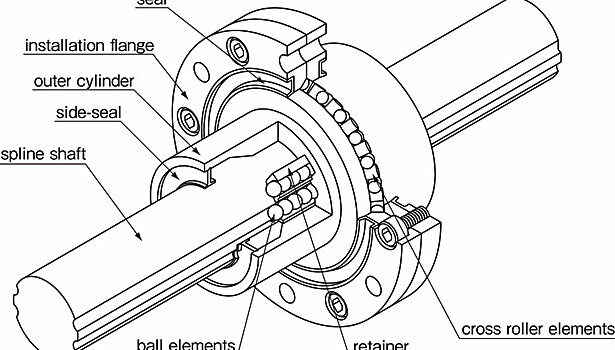
The rotary ball spline’s radial support bearing can be a crossed roller bearing or an angular contact bearing with two rows of balls. Crossed roller bearings are like ball bearings, except that they’re cylindrical rather than spherical. The rollers crisscross each other at a 90 degree angle and move inside V-shaped raceways ground into the outer diameter of the spline nut and the inner diameter of the rotary flange.
Whereas ball bearings provide single points of contact, crossed roller bearings provide lines of contact. As a result, crossed rollers can carry heavier loads than ball bearings. They also provide more rigidity, less deformation and more accuracy than balls.
Both angular contact bearings and crossed roller bearings can support the axial and radial loads that are typically encountered in ball spline applications. Where the angular contact bearing achieves this with two rows of balls, the crossed roller bearing does it with one row of rollers, but with some disadvantages, such as speed and wear.
Compared with the angular contact bearing, the crossed roller bearing is more compact. The spline nut itself is the same size either way.
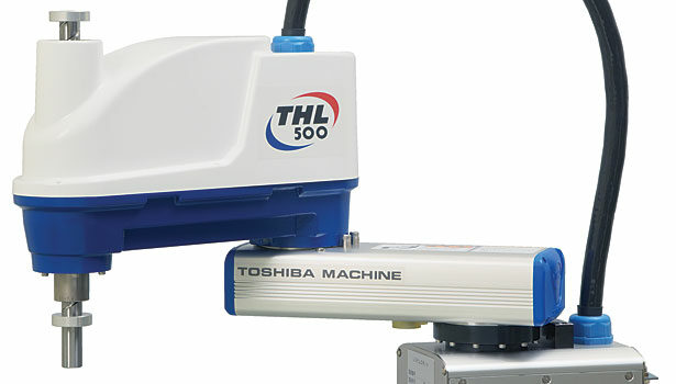
Crossed roller bearings are best-suited for high-load applications where space is at a premium and continuous rotation is not required. For example, a crossed roller bearing is a good choice for rotating a gripper in a pick-and-place operation.
In applications that require continuous rotation, crossed rollers wear out more quickly than ball bearings. For example, an angular contact bearing is a better choice for driving a grinding spindle, a conveyor belt or a wire winder.
For high-speed applications, angular contact bearings are more advantageous than crossed roller bearings. On a standard spline shaft 16 millimeters in diameter, a crossed roller bearing can reach a top speed of 1,080 rpm, while an angular contact bearing can reach 4,000 rpm.
Most existing rotary ball spline applications use angular contact bearings. Crossed roller bearings are relatively new for rotary ball splines. As a result, it can be difficult and expensive to retrofit crossed roller bearings into an existing application with angular contact bearings. Most rotary ball splines supported by angular contact bearings are interchangeable, at least from a size perspective.
