Ducati motorcycles are sleek, sporty and stylish. But don’t let their appearance fool you. Beneath the façade lies sophisticated motoring technology.
| Jump to: |
Indeed, 20 percent of Ducati’s global workforce of 1,000 people is dedicated to R&D. To keep some 200 manufacturing and design engineers on time and on the same page, Ducati relies on two products from Siemens PLM Software: NX CAD software and Teamcenter product life cycle management (PLM) software. Ducati uses NX to digitally model vehicle assembly. The company uses Teamcenter to share and distribute data securely, both in-house and with suppliers.
“We use NX from the moment we start thinking about a new project up to its completion,” explains Piero Guisti, Ducati’s information technology manager for R&D.
“NX is used to design many different motorbike components, including the wheels, chassis and the body…virtually everything except the engine.”
There are currently more than 50 NX workstations at Ducati. “The key benefits of NX are flexibility and ease of use,” Guisti says. “By ‘flexibility,’ I mean that it lets you generate 3D models with different methods, without constraining you to a fixed approach. NX with synchronous technology is a hybrid approach that avoids having to parameterize everything, so the user is free to choose how to achieve the final result.”
Ducati engineers use the 3D wiring functionality in NX extensively. It allows them to verify cable routing inside a virtual assembly, minimizing possible routing issues downstream.
“We can create wiring diagrams using the NX schematic functionality,” says Guisti. “After that, the diagram is passed on to the NX wiring application to incorporate all electrical information into the design. And finally, using the NX electrical routing function, we prepare the documentation for cabling installation. NX lets us cover the entire process with an integrated approach.”
“We use NX from the moment we start thinking about a new project up to its completion." |
Teamcenter has facilitated closer collaboration both within Ducati’s internal development teams as well as with external suppliers. “We increasingly need to exchange model data with suppliers,” explains Guisti. “With some of our long-term partners, we are investigating the possibility of providing them with direct access to the information in our system, so that we can further reduce development time by having them work in parallel with our designers.”
Within Ducati, the deployment of Teamcenter is already widespread. For example, Ducati has installed the software at its warehouse in Modena, Italy. Workers there perform minor assembly operations on finished bikes, typically installing body parts and custom elements. They use Teamcenter to view drawings, diagrams, documentation and assembly tables for all finished products.
Despite the increasing complexity of its products—a motorcycle might have seven electronic control units (ECUs)—Ducati has cut a year off development time for new bikes. “Our design and development cycle has been reduced from an average of 36 to 40 months to just 24 months, mainly thanks to the tools provided by Siemens PLM software,” says Guisti. “We are also able to update existing models at annual intervals. It would be unthinkable to achieve such results using conventional design methods.”
Siemens NX and Teamcenter are just one example of the sophisticated software available today to help engineers design and manufacture wire harnesses. Software developed specifically for wire harnesses, such as EPLAN Harness proD from EPLAN Software & Services LLC or Arcadia from Cadonix Ltd., are revolutionizing the process of electrical systems design.
Many CAD systems can define wire harnesses in a 3D model, but these models are not accompanied by electrical data, such as the number and diameter of the wires. Harness-specific design software does that—and more.
“When an electrical engineer is designing the wiring schematic for a new product, he’s not interested in the 3D model or the assembly,” says Doug Peters, NX product manager at Siemens PLM. “He’s just concerned with getting the right-sized wires connected to the right components.
“But to properly design the physical wire harness, you need more information. When you’re routing the harness through a structure, you need to know if it will fit. Is there something in the way? Is there a maximum allowable bend radius? Are there enough clips to secure the harness?”
EPLAN
EPLAN Harness proD is 3D software for designing and documenting wire harnesses. It can import wiring lists as well as mechanical CAD data in IGES or STEP format. It also imports the native data formats of all conventional CAD systems.
Engineers can define wire harness routes with an intuitive point-and-click method within the 3D space. The software can also automatically route harnesses on previously defined paths.
EPLAN Harness can automatically place parts based on preset criteria. For example, engineers could tell the software to insert a support clip on the harness every 12 inches.
The software automatically adjusts harness parameters if the geometry of a part changes. For example, say the harness passes over a subassembly. If the dimensions of the subassembly change, or if the harness is rerouted, the software automatically updates the harness dimensions to reflect that. The wire list and the form board drawing also amend themselves automatically.
The software can check a harness design based on user-defined criteria, such as bending radius limits, cross sections, and length restrictions.
EPLAN Harness automatically generates parts lists and bills of material. It can even estimate delivery dates and harness weight. It can output 2D production drawings, including 1-to-1 drawings for form boards and scaled drawings for service documents. And, it also generates control files for wire processing equipment, such as benchtop cutting and stripping machines.
Arcadia
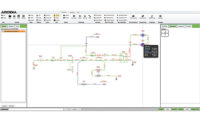
Arcadia is a cloud-based suite of CAD programs for electrical wiring design, analysis and report documentation. The suite consists of two programs: Arcadia Harness and Arcadia Schematic.
Arcadia Harness can be used as a stand-alone wire harness design and layout tool, or it can be used in conjunction with Arcadia Schematic.
Arcadia Harness includes a 2D drafting package, enabling the creation of a harness bundle layout. Connectivity data can be entered manually, imported from a structured wire list, or transferred directly from Arcadia Schematic. In the latter case, wire data will populate the harness bundles automatically.
Connector tables can be placed at the end of the bundle runs, and these tables are automatically annotated from the data brought in from Arcadia Schematic or a structured list. Graphical representations of the connectors can be shown either from a wire entry view, a face view, or isometric views.
Terminals, seals and plugs are selected automatically based on the wire and cavity size. Bundle diameters are automatically calculated based on the number and size of wires in each bundle segment. Splices can be positioned according to rules, and splice loadings can be optimized based on entry from the left or right side.
Wires can be moved from one cavity to another by simply picking up the end and relocating it. Any changes made during the layout of the harness are automatically back-annotated to the schematic.
Harnesses can be drawn 1-to-1 or not to scale (NTS). Various bundle finishes, such as tape or heat-shrink tubing, can be rendered in different levels of detail.
Mechanical components, including clips, grommets and brackets, can also be pictured. NTS drawings can be automatically converted to 1-to-1 at the touch of a button to create a full-scale form board. Harness segments and branches can be manipulated to fit into a form board of a specific size with branches being folded into position manually.
Arcadia Schematic lets engineers interactively place and connect electrical components to create schematic drawings that can then be used for real-time simulation and analysis. Engineers select components from a comprehensive library of intelligent symbols. The database includes wires, motors, lamps, in-line connectors, splices, terminals, switches, relays, fuses, diodes, LEDs, resistors, batteries, ECUs and ground points.
The software provides interactive feedback on the entire circuit through tool tips, and animated views provide instant feedback on electrical behavior. Engineers can draw, evaluate and test large, full-vehicle schematics spread across more than 100 sheets.
Real-time animated simulation paints a clear virtual picture of the electrical system and how it will behave under deployment. Engineers can confirm circuit loading, component function and error conditions through an animated graphical interface. The simulation can provide information on wire sizing, voltage drops, signal flow, short circuits, and the currents and times needed to blow fuses.
The benefit of simulation is that engineers can work on the electrical design simultaneously with the mechanical design. Physical prototypes are not necessary.
Arcadia can automatically generate a range of reports, including bills of material, connectivity lists, wire usage, and analysis reports. The software supports a variety of output formats, including IsoView-compatible SVG, linked PDF reports, and XML data. Using the document publishing tool, engineers can create custom PDF versions of the schematics ready to print, plot or publish. The PDFs are text-searchable, so it’s easy to find a particular component or signal of interest.
Because Arcadia is cloud-based, engineers can log-in to work from the office, home or anywhere.


