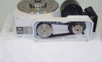
Rotary indexing table use is widespread in automated assembly machinery and selecting the proper mechanism is essential for both maximizing performance and minimizing the cost of this critical component. This how-to-guide will explore two common devices that can be used for rotary indexing and give advice for proper selection. These two popular devices are cam indexing drives and servo rotary tables.
Cam indexers are a ubiquitous mechanism that have been used for rotary tables for many decades. They are a great fit for applications that will always index the same angle and that require high-precision positioning at a very reasonable cost. A cam indexer uses a mechanical cam to provide the motion control to position the load. A mathematical motion curve is machined onto the cam that provides extremely smooth and repeatable motion.
A cam indexer has two main modes of operation. One mode is referred to as “Cycle-on-Demand”. This indicates that the camshaft will be cycled one revolution at a time to advance the output one position at a time. This is typically achieved by using an inexpensive camshaft sensor package to detect camshaft position and a VFD to stop and start the motor. The camshaft dwell period offers a wide window for the camshaft to stop without affecting the position of the output. To cycle the indexer, a PLC gives a command to the VFD to accelerate the drive motor to a preset speed, the cam rotates one revolution indexing the output, a sensor sends an in-position signal to the PLC, and the PLC signals the VFD to stop the camshaft during the cam dwell position. The table will be in the dwell position for however long is necessary to complete the work at each station. The dwell time can range from a fraction of a second to several minutes or hours depending on the application. This combination allows very accurate positioning with an inexpensive drive system.
A cam indexer can also be run in a more traditional “Continuous” mode where the camshaft spins at a constant speed and the indexing and dwell time is controlled solely by the cam motion profile. Continuous mode is useful when other equipment will be mechanically synchronized with the camshaft timing or when the indexer needs to run at cycle rates faster than a motor can be stopped and started. A continuous indexer can run at rates in excess of 1,000 cpm. The limitation of continuous mode is that it may be impossible to machine a cam that requires a quick indexing motion followed by a long dwell time.
A fully programmable servo rotary table is another common option. There are two specific cases where a servo rotary table is advantageous. The first is when a flexible motion pattern is required. An example is two different products being run on one machine that each require different indexing patterns. The other situation that suits a servo indexer is when extremely fast positioning is required followed by a long dwell period. A cycle-on-demand cam indexer is limited by the need to accelerate the camshaft up to speed during the dwell period before output motion is started. There are practical limitations to how fast the camshaft can be accelerated so there will be a delay before motion is started. With a servo rotary table, the output rotates as soon as the servomotor starts moving. A practical example would be a load being indexed 90 degrees in 0.25 seconds. This is not difficult for a continuous cam indexer or a zero-backlash servo indexer, but a cycle-on-demand cam indexer may struggle with that motion. For quick servo indexing applications, a preloaded gear reducer with zero-backlash is critical to achieving smooth indexing motions with minimal settling time. A zero-backlash RollerDrive mechanism would be an optimal choice to achieve accurate positioning with great dynamic response.
For either style of indexer, application information including moment of inertia, indexing angle, indexing time, and dwell time is required. A reputable manufacture should then be able to properly size the rotary table for the application.


