In industry, many repetitive operations—such as pick-and-place, spot welding and spray-painting—have been assumed by robotics. Even though the operations are diverse, a common thread runs through nearly all of them. The common thread is that the robot performing the task is permitted only limited physical contact with its environment. From a control perspective, this means the robot follows a desired trajectory precisely and reliably, ignoring interactive forces with the environment.
The common robot is a pick-and-place device. The robot and its end-of-arm tooling have to be flexible, in the sense that their design will readily accommodate modification. Frequently, the product or parts being handled in the workcell must also be flexible, in that same sense.
However, this type of robotic cell is not adaptable. Implementing cycle-to-cycle variations in part geometry or position, changeovers and design changes, and new part introductions pose significant cost issues. This adds significantly to the amount of money and time it takes to implement a robotic workcell. It also makes tooling a primary source of downtime, and adds to life cycle cell costs.
In contrast to pick-and-place operations, assembly tasks are fundamentally different in nature. Successful assembly requires precisely and delicately controlling the forces of interaction with the environment. This control is needed in such assembly operations as gear and spline meshing, threading fasteners and joining snap fittings. Humans currently perform such tactile tasks, because we naturally control our interactive forces. Typical industrial robots do not possess such compliance, so they generally fail—often miserably—at these tasks.
Current technologies used in robotic workcell applications don’t provide:
- Actively compliant and highly dexterous manipulator mechanical designs capable of enabling force control strategies and algorithms.
- Sophisticated and robust force control algorithms and strategies.
- Sufficient processor speed for on-line production use of advanced vision and force control algorithms.
- Sufficient algorithmic translations of industrial application spatial location and object orientation (pose estimation) to enable on-line 3D vision.
- A highly dexterous robotic manipulator with significantly less inertia and friction than commonly used manipulators.
- Robotic force control algorithms that react to contact forces to achieve reliable part assembly.
- Parallel processing techniques for robotic control.
- 3D pose estimation algorithms for robots that locate and pick randomly oriented parts from dunnage, and present the parts for assembly within factory floor cycle-time constraints.
Manipulator and Force Control
A novel parallel dexterous, hexapod-type manipulator, called ParaDex, performs the assembly tasks in the cell. ParaDex uses parallel mechanical architecture, with the motors fixed to the support structure. Therefore, large direct drive motors can be used without greatly increasing the moving mass of the robot. Using direct drive motors minimizes friction and reflected inertia. In any robot, actuator forces overcome internal friction, accelerate and decelerate internal masses and payloads, and generate interactive forces with the environment. By minimizing friction and internal inertia, more of the actuator force is available to control manipulation forces. The fully parallel architecture also provides high mechanical stiffness for quick and precise position control.Typically, fully parallel manipulators have limited workspace, in relation to the size of the manipulator. To alleviate this problem, ParaDex incorporates some important design concepts. A seventh rotary actuator drives the tool roll degree-of-freedom (DOF) independently of the other six linear actuators. This rotary actuator is fixed to the support structure and drives the tool roll through a prismatic joint and two universal joints separated by a shaft. While the six linear actuators are capable of providing six DOF motion, this redundant axis allows for unlimited range of motion of the tool roll. It also allows the six linear motors to effectively control the remaining five DOF with a larger workspace. The entire manipulator can be mounted in any configuration, but it is most often mounted inverted on an overhead support structure. In a typical assembly line, this puts the manipulator overhead so that it does not take up space on the factory floor.
Each of the ParaDex linear actuators is connected to the moving platform via a universal joint, a fixed length passive link and a spherical joint. Force sensors are embedded in the passive links. This mechanical arrangement ensures that the passive links remain in tension and compression with no bending loads. This provides high mechanical stiffness, with smaller, more compact links and bearings than would typically be required for a manipulator with equivalent payload. The joints are arranged in a configuration that improves the workspace and the dexterity of the manipulator.
The robot (ParaDex manipulator) is controlled by a personal computer (PC) with a real-time operating system, and a PMAC motion control board from Delta Tau Data Systems Inc. (Chatsworth, CA). Control switches seamlessly between precise position control and compliance control, based on whether the system is moving in free space or is in proximal contact with the environment. The position control mode uses built-in trajectory planning and smoothing algorithms on the PMAC. In this mode, the PC performs forward kinematics algorithm and workspace validation to avoid collisions. The PMAC plans and executes trajectories through and to commanded positions, including servo control.
The compliant motion control mode uses position and force feedback information to develop programmable behavior for the end effector. The end effector is made to behave like a programmable inertial object connected to a desired programmable trajectory by a set of programmable springs and dampers. The resulting motion is as if the entire robot were to be pulled along the path by the programmable springs and dampers.
In free space, the robot follows the path fairly closely, as in the position control mode. But if an object is encountered, the robot complies with the constraint imposed by the obstacle and pushes softly against the obstacle, trying to follow the path. If the obstacle is removed, or if the robot works its way past the obstacle, the robot will catch up with the desired path, and the programmable damping prevents overshoot or oscillation.
The PMAC puts each actuator in a straight velocity control mode with force "feedforward." All force and position signals are fed back to the PC at a servo rate of 2.2 kilohertz. The PC performs the computations to determine a desired acceleration for each actuator based on the sensed force and desired inertia, stiffness and damping. The desired accelerations are integrated to obtain desired velocities, which are downloaded to the PMAC for servo control.
Methods for teaching robots position-based tasks are well developed. But the same cannot be said for assembly operations. ParaDex includes a user interface and automated learning algorithms for assembly operations. The user interface incorporates standard teach pendant functions for programming the position-control-based portions of an assembly operation, such as part pickup, move to assembly start, return to pickup and return to home, as well as end effector control. The interface adds functions for teaching, and either manually inputting assembly search parameters or selecting them from a library of previously stored values. It also defines assembly completion criteria. This allows unskilled persons to program an assembly operation in about the same amount of time that it takes to program a standard robot to perform position-based operations.
While standard default assembly search parameters can be selected from a library, the resulting assembly Arial are not optimal. The number of search parameters used (typically eight or more) makes it difficult to manually adjust these parameters to improve assembly Arial. These parameters have no equivalent in position-control-type operations.
ParaDex has a learning algorithm that allows the robot to automatically search for an improved set of parameters within an allowable range for each parameter to minimize assembly time. Once a given assembly is successfully programmed, the robot is put in "learn" mode. During this time, the robot performs the operations repetitively without human intervention. Each time it changes the values for the search parameters and records the assembly time. This iterative process typically reduces assembly time by 50 percent or more.
3D Vision
FRAPA 3D vision differs from other vision guidance systems for robots in both the type of imaging sensor and the data interpretation methodology that are used.Traditional robot guidance systems use various imaging technologies. These include standard 2D intensity-based gray scale imaging cameras, stereo systems, structured light sensors and Moir?ensors. Image analysis methodology includes feature-finding methods, along with camera calibration, sensor rectification and robot-to-sensor calibration techniques. But these are greatly complicated by the weaknesses of intensity-based camera systems. These sensors are 2D devices operating in a 3D world. Unfortunately, 3D information has to be gathered from 2D data. However, there is no superlative way to do this, thus the proliferation of techniques.
FRAPA 3D vision incorporates a range sensor, which is commonly called lidar or optical radar, instead of the traditional camera. The proprietary range sensor, named LASAR, produces two images concurrently. The first is intensity-based. The second is a range map, which is also a gray scale image. However, the gray scale value represents distance from the sensor rather than intensity response. This range map provides information that can be directly related to scene surface height. With this information, 3D representations can be generated. Also, better geometric descriptions of the objects of interest can be created than with projection-based 2D imaging systems.
Standard image processing techniques deal with regions and edges. Range images produce 3D equivalents called surfaces and boundaries that are not well-suited for standard image processing methods.
A technique called tripod operators, which was developed at the Naval Research Laboratory in Washington, was adapted for FRAPA. Think of tripod operators as a structuring element, upon which a local coordinate frame that is part centric instead of sensor centric can be defined. Probes can be specified on this coordinate frame to create a feature vector that characterizes the local geometry. Because the feature vector is generated in the part coordinate frame, this object representation is invariant to part position. This feature vector can be used to recognize patterns in range images. By associating reference position vectors with the feature vector, it is possible to recognize the object and establish its full six DOF position estimate. This position estimate, called part pose, includes the X-Y-Z position, and roll, pitch, yaw orientation information. A tripod operator can be loosely thought of as a 3D correlation.
The key advantages of the range sensor-tripod operator approach are:
- The cell requires no teaching of points. Once the sensor and robot coordinate frames are synchronized, the vision system finds part locations and gives position information to the robot in robot coordinates.
- The cell can be prebuilt up to the gripper. Only general knowledge of the parts to be handled is necessary. Only the size of the part and size of the dunnage are required to configure and price the cell.
- New part models can be created on a teach-by-showing basis in a matter of minutes. This means that the time to introduce a new product is only determined by the time required to build a new gripper, not the time to build a cell.
- The plan provides a generic vision approach to locating parts in random orientations.
FRAPA at Work
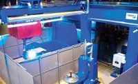
The integrated robotic workcell was installed at Comau PICO in Southfield, MI. One 3D vision-guided robot picks randomly oriented power train parts from dunnage and hands the parts directly to the ParaDex. It assembles the part or parts into the mating power train components, using its force control and compliance capabilities.The FRAPA demonstrates that future flexible manufacturing and assembly technology will:
- Handle heavy payloads reliably, smoothly and delicately without damage and with little human intervention.
- Adapt to assembly tasks through human teaching and machine self-learning.
- Focus on smart machines with inexpensive end-of-arm tooling. This will allow economic recovery of capital investment. Capital equipment will be long-lived, flexible and adaptable assets.
- Perform complex, delicate, force-controlled, highly precise assembly tasks without human intervention in X-Y-Z axes, with high reliability and repeatability, and without precise position material delivery requirements.
- Eliminate part-specific delivery automation.
- Interact compliantly with a human.
- Simplify product adaptability and changeover.
- Assemble automatically a product designed for manual assembly.
- Perform quality control tasks simultaneously with assembly operations.


