
 When determining the proper linear transfer system there are some key factors that will help determine what is appropriate for your specific application.
Here are some things that will affect accuracy and repeatability of a linear transfer system.
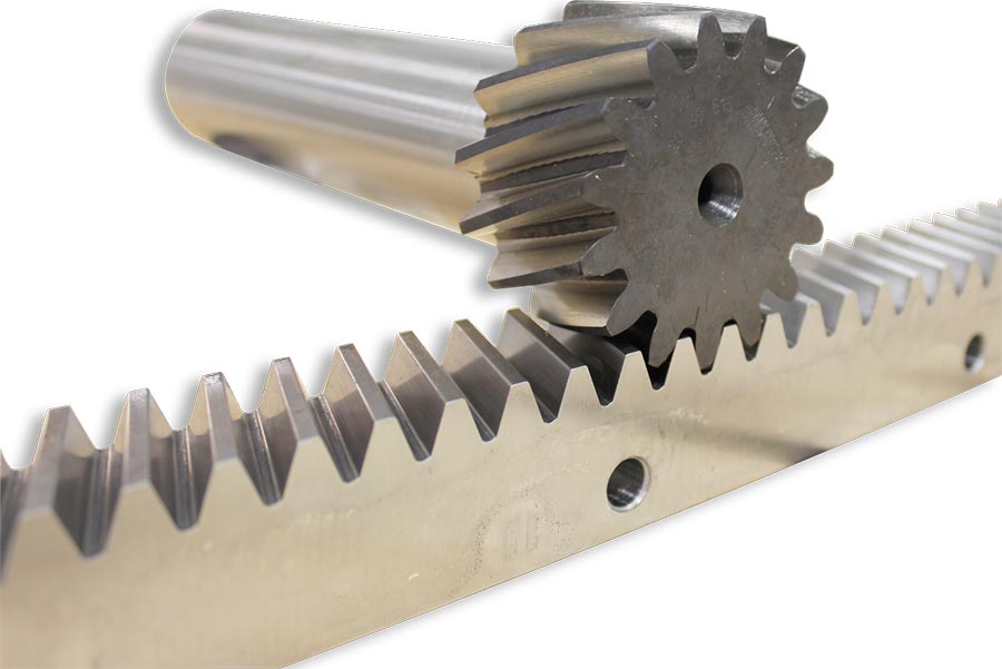
Rack and Pinion System
- Backlash in gear reducer – can range from <1 arc minute to >18 arc minutes
- Back lash between rack and pinion system – higher quality offers greater accuracy
- Proper preload / assembly of rack and pinion system
- Number of encoder counts per revolution of motor
- Proper commissioning of drive parameters controlling servo or AC motor with encoder
At Motion Index Drives each application is unique and is specific to each customer, when discussing your application, we take an approach to finding out exactly what the customer’s true needs are. The systems Motion Index Drives manufactures can be purchased to the length required for the application. When the speed of transfer, accuracy and total moving mass is known, a complete engineering study will be performed to right size the rack and pinion system for the customer. We make sure to have at a minimum a 2:1 safety factor on for each system.
The linear bearings or guiding system will also affect overall accuracy of the system. Some manufacturers of linear bearings offer different options of accuracy in the same size rail. In regards to parallelism, the offerings can range from 9 microns to more than 30 over a span of 3000 mm.
What information is needed to properly size the linear guiding system?
The linear guiding system is what allows the rack and pinion system to propel the carriage back and forth. When properly sizing the guiding system it is important to know a few key elements.
- What is the overall weight that will be transported?
- How fast does this weight need to be transported m/s?
- What is the center of gravity of the moving mass?
- Is there a tilting moment and is yes, what is it?
- What is the overall duty cycle requirements?
- What is the expected life cycle?
- Will the system be operating in a harsh environment?
When all the loading data is determined a calculation should be completed to ensure proper sizing of guiding system for the application.
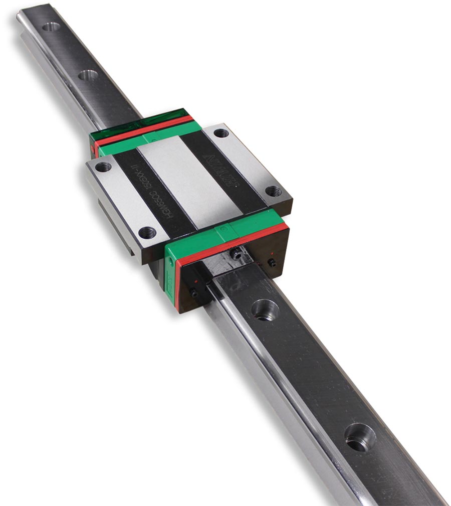
Linear Guide
With all commercial components there are differences between manufacturers of linear bearings as well as differences in quality. It is important to understand certain features of each and how it will impact your process.
- What is the specification on run out of the linear guiding system?
- Can single sections of rail be changed out?
- Is there and option to have self-lubrication?
- Does the manufacturer have protective bellows as an option, if needed?
Motion Index Drives linear transfer systems use high quality linear bearing systems that are ground precisely to allow for individual sections to be changed out opposed having to change entire spans of bearings that some manufactures suggest have to be ground as matching pairs. This can become an expensive and time consuming process. By having high quality, very precise bearing systems, that can be changed out, in case of a damaged section, will allow for quick MTTR.
What type of process will it be?
There are many different uses for linear transfer devices from material handling to vision system to welding robots, painting and others. The process will determine how the transfer system must be protected, how the cable management system must be constructed and what the proper components that must be used are. For example, explosion proof motors for painting applications.
In a paint process, extensive protection of the components would be required. Full bellows to protect the linear guides and power and communication cables would be a requirement.
With the ability to speak directly to the manufacture, a Motion Index Drives sales engineer will get to understand your process and guide you through and suggest the necessary protection and features required that are specific for your application to ensure a long life cycle for the linear transfer system.
How does the process affect the cable management system?
Knowing the process will determine what type and how large the cable management system must be. If the application is a material handling robot application the amount of utilities going through the cable management system will be comprised of robot communication cable, robot power cable, air line for end effector, power cable for carriage motor and communication for carriage motor.
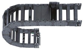
Cable Management System
For welding applications, where the welding robot will be on the linear transfer system, large diameter welding cables will have to be carried through the cable management system. It is extremely critical to make sure these lines are flex lines suited for 7th axis linear slide systems. These large diameter cables can cause serious problems by destroying an improperly sized cable management system or the lines themselves can get destroyed in a cable management system that isn’t designed with the proper bend radius. This scenario can cause a serious safety issue.
The bend radius requirement can have an impact on the linear floor space that maybe needed for the completed systems. Sometimes this small, but very important detail is overlooked and design layouts will not initial add a properly sized cable management system. As the bend radius increases, this will cause the cable management system to protrude outwards away from the end of the rails when the carriage is fully retracted.
At Motion Index Drives we understand the importance of getting this commonly overlooked component correctly engineered. We take the time to understand exactly what type of utilities will be passing through the cable management system. When we know exactly from the customer what type of utilities will be carried by the cable management system, we engineer and design the system to have the proper bend radius and spacing requirements. By properly designing the cable management system with the proper bend radius, maximizes the life of the utility lines. Premature breakdown of the utility lines passing through the cable management system can cause many hours of downtime. We take every precaution we can to make sure we engineer the right system.
Ben Talan,
President
p. 888.328.9853
www.motionindexdrives.com
info@mid.us.com