Leak Testing Plastics
Every day, more and more products are being made from plastic. This includes components and assemblies that need to contain or exclude fluids and gases. The classic example is the automotive fuel tank, a structure once made exclusively of metal. The medical sector also makes heavy use of plastics in everything from vials to catheters to implanted devices, such as pacemakers. The same is true of appliance manufacturers.
Unfortunately, engineers often face a number of challenges when leak testing plastic parts. Granted, if you are going to perform a simple dunk test, in which the part is immersed in water and then checked for bubbles, you don’t have to worry about a component’s particular properties.
However, today’s manufacturers require far more precision and efficiency than is possible using this time-honored method. For all that the basic idea behind leak testing is a simple one, implementing a leak-test system that is reliable and effective requires careful forethought and planning.

Manufacturers often use tracer-gas systems to test for leaks in larger plastic assemblies, like fuel tanks. Photo courtesy VIC Leak Detection
Flex Time
First and foremost, when leak testing plastic assemblies, engineers have to contend with the fact that they are often dealing with only semirigid parts. Flexibility may be all the rage elsewhere on a production line. But, when it comes to leak testing a particular product, engineers want things to be as constant as possible.The reason is that most leak-test systems depend on creating a pressure differential between the inside and outside of a part. For example, in a pressure-decay leak test, the system pressurizes the cavity being tested and then takes multiple readings to see how fast the pressure drops. Similarly, in a vacuum-decay test, an operator pulls a vacuum and then uses precision instruments to see how fast the pressure rises as nature does its best to do away with that which it abhors. In either situation, any flexing or expansion of a thin-walled plastic structure can create the illusion of a leak as it affects the pressure differential.
Fortunately, by taking a close look at an assembly’s specific leak-testing requirements, engineers can usually find a way around these challenges. For example, while Andrew Tapper, engineering manager at plastic welding equipment company Forward Technology (Cokato, MN), agrees that distortion, or “creep,” can be a problem, he points out that it is fairly repeatable during normal production and can therefore be compensated for.
“Where creep can be seen the most is in the repeat testing of the same part,” Tapper says. “This is probably the biggest difference between testing plastic and metal assemblies. Since plastic tends to take a set… the creep is never quite the same as it was the first time it was pressurized. This makes the use of a ‘master’ good plastic part assembly something I never recommend.”
Similarly, although Alan Campbell, global technical support manager for Uson L.P. (Houston), describes elasticity as one of the primary differences between testing plastic and metallic components, he emphasizes there are ways to compensate for these properties, and that the problem varies widely, depending on the assembly.
“In many cases, physical or mechanical stops may be required to restrain the product under test, as with, say, a medical flask or something similar,” he says. “[But] smaller products such as medical Luer-type fittings lend themselves to pressure-decay type testing very well, as do cell phone housing assemblies and the like. Generally, this all gets down to wall thickness, test pressure, product design, etc. Many plastic components will have designed-in ribs for reinforcement and are much less likely to move or creep under test.”
In fact, Jacques Hoffmann, president of InterTech Development Co. (Skokie, IL), argues that in the end, despite its elasticity, plastic isn’t that much different from metals in some situations. According to Hoffmann, “The material that the part is made of-metal or plastic-is not what creates creep. Rather, it depends on the volume and wall thickness of the part, and the test pressure and how the volume of the part relates to the size of the leak you are measuring…. Creep can be a problem with a metal fuel tank just as much as it could with many plastic parts.”
That having been said, engineers need to bear in mind that, in addition to accuracy issues, creep can also result in cycle-time problems, as each assembly has to wait and reach a stable point before it can be tested. However, in these instances, engineers can opt for a dynamic testing system, like the Signature Analysis approach developed by Sciemetric Instruments Inc. (Ottawa, Ontario). Using this technology, the leak-test system evaluates the entire test cycle, including the fill, test and even exhaust periods, all the while checking for anomalies. This makes it possible to check an assembly without having to wait.
“One of the great benefits of using Signature Analysis and understanding leak-test waveforms is that it can help compensate effectively for [cycle time] challenges,” says Sciemetric founder, Nathan Sheaff. “Large populations of leak signatures for both good and bad parts can be analytically compared with software…to allow statistically sound and reliable pass-fail algorithms to be determined quickly.”
Then again, engineers can always solve both the cycle-time problem and the creep conundrum by going with a test system that uses a tracer gas, like hydrogen or helium. According to Ray Hula, leak detection specialist at Varian Inc. (Palo Alto, CA) this approach is less sensitive to volume variation because it directly measures the amount of gas leaking from an assembly, as opposed to inferring the presence of a leak from a pressure change. It also requires a smaller pressure differential between the inside and outside of the test part.
On the down side, this approach is generally more costly than air-based methods, thanks to the sensor technology involved and the fact that it uses a consumable gas. But, according to David Morris, marketing manager at Alcatel Vacuum Products Inc. (Hingham, MA), it is also extremely sensitive, fast, accurate and reliable, which often makes it worth the extra expense.

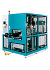
In addition to indicating the presence of leaks, tracer-gas systems, like this hydrogen model, can be used to detect their location. Photo courtesy Alcatel Vacuum Products Inc.
Keeping Cool
Another factor engineers need to keep in mind when leak testing plastic parts is heat, at least when using air-based methods. Although tracer-gas technologies are relatively immune to temperature variations, air-based leak tests are subject to the Ideal Gas Law, and pressure, volume and temperature are interrelated. According to Bill Hathaway, sales manager for the air leak testing division at VIC Leak Detection (Dayton, OH), variations can lead to poor repeatability, masking leaks or “virtual” leaks, in which pressure changes imply a leak where none exists. Temperature can be especially problematic when performing inline testing with recently molded parts, or parts that have recently been assembled using techniques that produce heat in the part such as spin or ultrasonic welding.“Because plastics are insulators that do not readily dispense heat, any freshly molded part that has not been allowed to cool off will affect test results if the leak-test instrument does not have built-in temperature compensation abilities,” says Hoffmann, adding that leak-test instruments that do not have customized sensors or built-in mechanisms to compensate for temperature effects will not be able to achieve a very high standard.
Greg Popp, vice president of sales at Cincinnati Test Systems (Cleves, OH), agrees, saying that in these cases it is important to employ testing equipment that can account for temperature, part characteristics and other environmental conditions.
“Ideally…you want your part as stable as possible during the test to achieve repeatability,” Popp says. “The slower heat transfers, the better the test. It is always best to test at ambient temperature if at all possible.”
Tapper, whose company manufactures in-line test systems to complement its plastic welding machines, notes that the type of assembly process being used can influence the way heat will be distributed in an assembly.
“With plastic parts, the type of welding process has a large effect not only on the residual heat left, but also how the part cools,” Tapper says. “Hot plate welding generally heats the entire part a great deal, requiring a great deal of cooling before testing. Ultrasonic, vibration and spin welding processes create heat localized at the weld joint. As this heat migrates through the part after welding, it can have quite surprising effects on leak-test results. Basically, the best general rule for leak testing plastic assemblies is, ‘cool and consistent makes for the best results.’”
Tapper adds that while higher temperatures can be compensated for, the higher the temperature, the faster the part will cool, making repeatability much more difficult. “Often queuing parts between 10 and 30 minutes is enough to make pressure decay results substantially more repeatable,” he says.
Other Factors
Any leak-testing technology can be used to check plastic assemblies. However, because many plastic assemblies aren’t required to meet the same rigorous standards as, say, a more expensive stainless steel component, they are often tested using basic vacuum- and pressure-decay methods.Small parts, in particular, lend themselves to these approaches, because of the low gas volumes involved and the fact that they are inherently stiffer than larger assemblies.
Hoffman notes that in some instances engineers might want to consider using the mass-flow approach, in which a test part is brought up to a certain pressure after which a sensor measures the amount of air needed to keep it at that level. This technique offers a number of advantages, among them, the fact that it requires a single measurement-the airflow rate at a given instant-as opposed to the multiple measurements required to determine the rate of pressure or vacuum decay.
Hathaway agrees, noting that mass-flow systems can be especially effective when testing larger parts.
“Since mass flow is a direct reading in leak-rate units, as soon as the overall leak rate-including volume expansion, adiabatic stabilization, part leak, etc.-falls under the reject value, the part can be accepted,” Hathaway says. “The part can be tested more quickly with an actual measurement vs. a predicted value.”
For larger parts or parts that need to meet especially high leak-rate standards, engineers should consider using hydrogen and helium. These gases work well in more demanding applications, because their small molecular size allows them to ferret out small leaks more quickly than air. They also, as noted earlier, are fairly insensitive to temperature variation.
For example, Alcatel’s Morris says tracer-gas methods are often used with medical tube sets and catheters, which both have very tight leak specifications. He warns that hydrogen will occasionally permeate some very thin plastic materials, but this can easily be compensated for because the seepage is typically uniform from one part to the next.
Morris adds that, while some tracer gases will stick to plastic surfaces, hydrogen’s high energy allows it to escape quickly and easily from the part being tested. He says helium is more prone to sticking, but can still be used effectively.
At the other end of the volume spectrum, the tracer-gas approach is often used to test large-volume assemblies like automotive fuel tanks, which have flexible sides that make air-based tests problematic. For example, Chris Goebel, director of component sales at helium test manufacturer ULVAC Technologies Inc. (Metheun, MA), says tracer-gas technologies are becoming increasingly popular in response to government mandates calling for higher and higher environmental standards.
“Strict EPA greenhouse gas emission regulations mandate very small leak rates in fuel system related plastic parts, such as gas tanks and fuel sending units,” Goebel says. “As clean air standards increase, we expect that smaller leak rates will need to be measured, which will increase the usage of helium tracer gas leak detection methods for these plastic parts.”
“Typically the bigger the part the more tendencies there are to use a tracer gas,” agrees Cincinnati Test Systems’ Popp. “The smaller the parts, the more tendencies there are to use pressure-decay or mass-flow technology.”
According to Varian’s Hula, another advantage of using a tracer gas is that operators can easily pinpoint the exact location of the leak using a handheld sniffer probe. In some settings, a single system can be equipped with multiple probes to locate leak points automatically.

As is the case with all precision leak testing, effective fixturing plays an important role in ensuring reliable results. Photo courtesy Forward Technology
Odds and Ends
Finally, when implementing a leak-test application, engineers should not overlook the questions of fixturing, sealing and the “direction” of the test.As with leak testing in general, it is important to test in such a way that the part or assembly is subjected to forces similar to those it will experience when in use. Testing in the wrong direction may compress cracks or holes enough to create a temporary seal.
To illustrate, Uson’s Campbell cites the example of a medical flask that has been welded together ultrasonically. “[This assembly] will most likely be tested with a positive internal pressure in order to stress the weld, rather than a negative pressure that might actually assist in masking the leak,” he says.
ULVAC’s Goebel notes that this is another area in which the tracer-gas approach offers a possible solution, especially in more challenging applications, because of the minimal pressures involved. “Advances in tracer-gas leak detection are now able to permit testing at a slightly negative pressure, just below atmospheric. Using just slightly negative pressures for leak testing means the plastic parts are not subjected to the large pressure differentials that can distort or crush them altogether,” he says.
With regard to tooling, it’s important to fixture the parts in such a way that the tooling does not block possible defects. According to Popp, “You do not want to press against joints, possibly sealing the leak, thus allowing bad parts to get through the process.”
Hoffmann agrees, noting, “Every part requires unique fixturing solutions.... The breadth of experience one brings to creating test fixtures has a great bearing on ultimate success.”
Then there is the matter of creating a seal between the test part and the pump that is applying pressure or pulling a vacuum. On the one hand, you don’t want any leaks. But, you don’t want to crush or distort the part either. This can be especially difficult with larger parts or sealing areas. Popp recommends pneumatically activated inner- or outer-diameter seals as one way engineers can minimize these kinds of problems.
Varian’s Hula notes that no matter what the seal, it needs to remain constant when performing an air-based leak test to avoid creating virtual leaks. For example, O-ring creep will have the same effect on results as creep in the test part. According to Hula, this is another area in which opting to use a tracer-gas may help solve a manufacturer’s problems. Basically, because tracer gases don’t depend on recording pressure changes, the fact that a system has to charge a part a little more or less to bring it up to the correct test pressure is irrelevant. “As a result, the fixating doesn’t have to be as exact,” Hula says.
Along these same lines, Forward Technology’s Tapper warns that engineers need to be wary of small knit lines, which can cause problems if they occur across the sealing surface. “Even mold ‘hairs’ can contaminate sealing surfaces enough to disrupt effective testing,” Tapper says.
Finally, to speed up cycle time, engineers should minimize the volume of air being monitored, so that they will be pressurizing or pulling a vacuum on a smaller space.
“Whenever possible, the internal air volume of the part under test should be reduced by using, for example, a mandrel. It is also always best to minimize the total pneumatic circuit volume and use short lengths of tubing where possible,” says Sciemetric’s Sheaff.
Looking for a reprint of this article?
From high-res PDFs to custom plaques, order your copy today!


