Join us on this walk down the memory lane of “putting things together!”
ASSEMBLY was born in October 1958 with the nameAssembly & Fastener Engineering. Although its name was later shortened toAssembly Engineering, and subsequently to ASSEMBLY, it was then, and is today, a magazine of ideas and methods: a forum where manufacturing and design engineers can find and share practical knowledge about tools and techniques for joining piece parts into finished products. From the archives, here’s a snapshot of people, machines and tools, and some of the things they’ve assembled in the past half-century.
In The Beginning
It isn’t only a matter of putting parts together. “Not long ago the electric window on my brand-new beautiful automobile refused to roll up in a sleet storm. It provided less shelter than a $2 umbrella,” wrote H. Thomas Hallowell Jr., president of Standard Pressed Steel Co., to begin the first article in the first issue ofAssembly & Fastener Engineering, October 1958.After commenting on the dismal failure of his car’s electric window, Hallowell asked, “Must we pay a yearly $16 billion repair and service bill? Are we meeting tomorrow’s competition and needs with products doomed to failure even before they leave the line?” In addressing the pressing concern of product reliability, he pointed out something as true today as it was then: “Management must stop looking for a low initial purchase price of an item. Too often the lowest price has won out only to lose the battle in service, to the detriment of the manufacturer and the customer. The cost of the item must be measured in terms of final reliability.”
Blind Fasteners Preserve Appearance
The Westfield Manufacturing Co. had established a solid reputation building Columbia bicycles. But, as the firm began feeling the effect of imports on the market, management decided it needed another line of products. It turned out that the plant equipment and production cycles in place could easily be adapted to producing school furniture because both products were based on tubular steel frames. Beginning with steel strip, the plant manufactured steel tubing, formed the required shapes on standard tube-binding machines, and welded or brazed the parts into finished frames. Parts for chairs and desks were made with the same process, but assembly was a different matter.In November 1958, Lawrence A. Maher, factory manager, explained that fasteners were needed that would stand up to the rough use given the furniture by school children. Another concern was customer demand for unmarred frames. Both concerns were alleviated by switching to Pop rivets-blind fasteners inserted and set from one side of the mating parts using a power rivet gun. “Integrating this fastener into our assembly operations has doubled production on some furniture models,” Maher said.
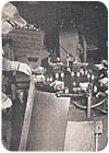
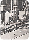
This automatic machine brazed auto heaters at Blackstone.
Brazing Machine Outperforms Torches
A builder of household laundry equipment since 1874, and one of the first to build a successful automatic washer, the Blackstone Corp. (Jamestown, NY) was also a long-time supplier to the automotive industry, particularly radiators and heaters. One of the difficult challenges involved in assembling a heater was hand soldering the top tank to the heater core, a slow and expensive operation. Labor costs and rejects due to leaks were high, adding additional inspection and rework costs.In January 1959, Paul Crespy, production superintendent, described how the firm met this challenge by installing a nine-station self-indexing automatic brazing machine. The top tank, a subassembly of the heater core, came to the brazing machine with several other components already installed. The operator added remaining components, placed preformed rings of silver brazing alloy where needed, added flux, and started the machine cycle. Preformed rings and other shapes of brazing alloy were used to assure optimum quantity of filler in every joint. “One man produces as much with this machine as five men did by the former hand torch method,” Crespy said, “and quality has improved to the point where there are practically no rejects or rework.”
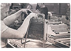
Self-tapping screws cut costs at Royal McBee.
Self-Tapping Screws Cut Costs
Only us dinosaurs remember manual typewriters, but they were once the mainstay in any office. Royal McBee Corp. was building hundreds of thousands of them annually in February 1959, when Henry J. Teller, supervisor of assembly standards, related how the firm saved $10,000 in assembly costs in just one year by using self-tapping screws.In one application, from two to four self-tapping screws, depending on the model of typewriter, were used to fasten a plastic spacing bar to a steel bar frame. Machine screws had previously been used, which required drilling, reaming and tapping. Worse yet, inserting screws at an angle, or running the screws down too hard with the automatic screwdriver, turned an assembly into scrap. Self-tapping screws were also adapted to joining top cover hinges and latches on both standard and electric typewriters. In addition to the $10,000 savings in labor and waste reduction, the move also freed up the tapping machine for other work. “In the 1-year period, we used more than 2.5 million self-tapping screws,” Teller said. “The saving per screw was infinitesimal, but it amounted to a worthwhile saving in a year’s time.”
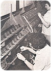
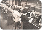
Four teams of two ladies each assembled a complete wiring harness for a Kimball organ.
Standard Wiring Eliminates Confusion
During its first 100 years, the W.W. Kimball Co. built more than 7,000 pipe organs, many shipped to far corners of the world. But by the 1950s, labor and material costs no longer permitted the firm to build these fine instruments, and Kimball turned to manufacturing electronic organs. These organs used a light beam passing through rotating slotted plates to generate tones of various frequencies, and Kimball claimed that they reproduced the tones of real pipes almost exactly. Wiring the myriad photoelectric detectors, keys, pedals, printed circuit boards (the tone generators) and amplifiers was a major challenge.An article in the July 1959 issue described how Kimball met this challenge by standardizing wiring harness assembly. A complete set of tone generator boards for one model organ was placed on a workstation, and a complete set of switches for both keys and pedals was placed on an adjacent workstation. Spools of color-coded wire and all necessary tools were readily at hand. Four teams, each comprised of two ladies, worked in sequence to assemble a complete wiring harness. The reason for this was that Kimball learned that the optimum number of wires for a team of two to lay up and solder was about 100. More than that number made training difficult because of the number of connections to remember, and also led to fatigue; less caused too-frequent team shifts. Once each team had completed its work, the complete wiring harness was removed and the cycle began anew.
The fuselage was lowered onto the completed wing of a DC-8 and mated in only a few minutes.
The DC-8 Takes Wing
In September 1959, D. H. Voss, general superintendent of Douglas Aircraft Co.’s DC-8 Facility (Long Beach, CA), brought our readers a superbly illustrated description of building the DC-8, from radome to tail cone. Voss pointed out that that there was no prototype airplane. When the first DC-8 took to the air in 1958, airplanes number 2 through 14 were already in production. Long fatigue life and fail-safe assurance were the major structural quality goals for the DC-8, and achieving those goals stood at the forefront in every aspect of manufacturing the airplane, from making the parts to final assembly. For example, the left and right wings were built separately and then joined at what would become the centerline of the airplane fuselage. Centerline joining eliminates wing roots on each side of the fuselage and provides a stronger overall structure. The completed fuselage was then lowered onto and mated with the finished wing.Another measure to extend fatigue life of the DC-8 wing was using Drivmatic machines to automatically drill and rivet the skin to the stringers in one operation. This assured uniformity and even stress distribution, and made the DC-8 wing tank assembly a single structure of unique integrity and strength. Douglas-designed riveting machines attached fuselage skin sections to frames, stringers and doublers. Rivets were upset into countersunk cavities and shaved smooth to reduce parasitic drag in flight.
Designing and building the DC-8 required close collaboration among people widely separated geographically. In a harbinger of globalization, Voss said: “Although engineering and production responsibilities are separated by a distance of 31 miles, no coordination difficulties have been encountered by the thousands of men and women participating in the program.”
In-line riveting machines assembled the coupler and wheel carriage for a Lionel train.
Riveting Saves Cost
Critical issues in selecting equipment for assembling toys are operating speed, capital cost and adaptability to a variety of assembly tasks. An article in the November 1959 issue described how Lionel Corp. (Irvington, NJ) used automatic riveting for assembling many of the components in the firm’s toy trains.Because the firm was using nearly 40 million semitubular and tubular rivets to assemble its trains, and because competition mandated a brief design life, Lionel was constantly refining its assembly methods. The products are relatively small, and mainly assembled with rivets, so the firm used bench-mounted electrically driven riveting machines extensively. Most were single-spindle machines, favored because tooling and fixtures were economical, and operators could easily orient parts correctly. Consequently, acceptable production rates could be maintained even though only one rivet was set on each machine cycle. Rates of more than 800 rivets set per hour were commonplace at Lionel for these basic single-spindle machines.
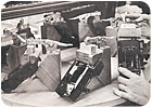
An operator cemented Kodak nameplates to camera cases in this eight-station fixture.
When Film Was King
Photographic film is rapidly going the way of the buggy whip, but before the advent of microelectronics, photography meant exposing film to light. The tool for doing that was the camera, and the market leader in the United States was the Eastman Kodak Co. In February 1960, Milt Cherkasy, product engineer in the firm’s Apparatus & Optical Div. Camera Works, described what was involved in assembling the Signet 80 35mm camera.The camera weighed only 24 ounces, yet comprised more than 180 parts-with each of the 29 subassemblies counting as one part. One subassembly alone-the shutter mechanism-contained 80 components. Most parts were joined with either adhesives or threaded fasteners, with clinched lugs, retaining rings and formed fasteners used in a few places. Simple tooling was the order of the day. One example was a rotating fixture for cementing the nameplate to the camera case. An operator joined the parts with adhesive and placed them in a De-Sta-Co clamping block. The adhesive cured in one rotation of the eight-station fixture.
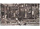
Engine blocks moved along the world’s longest diesel engine assembly line in the Kama River Plant.
Assembly in Europe
Several reports on European assembly plants appeared in the 1970s. An article in the August 1975 issue profiled the Kama River Truck Plant in Russia. The centerpiece was a review of the world’s longest automatic assembly line-780 feet overall-for diesel truck engines. The highly mechanized line was manufactured by the Automatic Production Systems Div. of the Ingersoll-Rand Co.The line had several unique features for the time, including a system that automatically set valve lash to ±0.001 inch, which was vital to optimum engine performance. Another was an operation that automatically selected connecting rod and piston assemblies for each individual cylinder to yield the desired compression ratio.
In the February 1977 issue, another article reported on a tour of the Fiat plants in Turin, Italy. Automation was everywhere, and it was evident that managers and engineers were believers when it came to taking full advantage of up-to-date assembly technology.
Robots, assembly machines, transfer lines and other contemporary equipment illustrated Fiat’s philosophy of aggressively pursuing high-reliability manufacturing at optimum cost. The premier example was the firm’s use of sophisticated electronically controlled fastening equipment to ensure that the threaded fasteners used for critical joints were accurately tightened to the correct torque specifications.
Surface Mount Arrives
The rapidly advancing use of surface mount components was the major issue for electronics assembly in the 1980s. Although traditional manual assembly of through-hole components remained practical in some cases, it became increasingly evident that surface mount components could not realistically be assembled manually in mass production quantities. A special issue in May 1986 explored the subject of surface mount in depth.Surface mount technology, by its very nature, required then-as now-a re-evaluation of assembly techniques. The diminutive size and ever-increasing density of components on the printed circuit board precluded manual assembly except for the simplest or one-off products. Robots, computer-controlled placement machines and machine vision were combined to meet the need for rapid and reliable production. Although through-hole technology was widely predicted to disappear from the scene by the turn of the century, this proved to be-as Mark Twain once said about reports of his demise-premature.
Looking Ahead
We believe in the future of American manufacturing, but in the inimitable words of Yogi Berra, “Predictions are difficult, especially about the future.” We don’t know what the manufacturing scene will look like 50 years from now, but ASSEMBLY will be there, serving engineers in American manufacturing with information to help them do their jobs better and advance their careers, just as we’ve been doing for these past 50 years.Of one thing, however, we can be sure. “Machines,” wrote Elisha Otis, “are the tools of liberty.” Which leads us to a final note, the touchstone unswervingly held by someone I admired greatly-the late Robert Bartley, long-time editor ofThe Wall Street Journal: “Free markets; free people.” I’d like to believe that ASSEMBLY magazine has played a role, however small, in supporting that principle, and you can depend on us to continue doing so.
A Show Is Born
The genesis of what we know today as Assembly Technology Expo was a cooperative event betweenAssembly Engineeringmagazine and the Society of Manufacturing Engineers. Called Assemblex 74, it was held in November 1974 in Arlington Heights, IL. Assemblex moved to a different venue each year; in October 1975 it was held at the Holiday Inn O’Hare, and in October 1976 at the newly opened O’Hare Expo Center, both in Rosemont, IL. In October 1977 Assemblex 77 was part of SME’s Autofact I, held at Cobo Hall in Detroit. In November 1978, Assemblex 78 took place in Cincinnati, and in October 1979, Assemblex 79 was part of Autofact II, held at Cobo Hall.The show acquired a new name and new management the following year. The Assembly Engineering & Manufacturing Conference and Exhibit debuted at the O’Hare Expo Center in September 1980, managed by Professional Exhibition and Management Co. [PEMCO] under contract withAssembly Engineering’sparent, the Hitchcock Publishing Co. The show has been held at the O’Hare Expo Center, now the Donald E. Stephens Convention Center, ever since, with regional events held elsewhere.
In September 1983, Assembly Technology Expo (ATExpo) acquired the name that continues to this day. ATExpo acquired new management, Reed Exhibition Co., when the show was acquired by Reed Elsevier in 1998. ATExpo was subsequently acquired in 2006 by its current owner, Canon Communications LLC (Los Angeles). In September 2007, for the first time, ATExpo was co-located with Quality Expo, the Electronics Assembly Show, National Manufacturing Week and PlasTec Midwest, at the Donald E. Stephens Convention Center.
Some Things Never Change
Leo Spector, then editor ofAssembly & Fastener Engineering, wrote these words on the fine art of foot dragging in January 1963:Object: To give you the upper hand with design, engineering, and production people, and to make you look good in the eyes of management.
The secret here is to create the impression of a loyal employee devoted to the company’s interests. Challenge everything new-product, method, equipment-and force a compromise. Then, settle for a watered-down version. Justify this by a few words about reducing costs, speeding up production, and, if you want to pull out all the stops, keeping up good oldstatus quo.
Of course, you must be prepared for some unpleasantness from time to time. You may be accused of tampering with product quality, of being old fashioned, of having a closed mind, and, even, of being a stubborn fool. There are several pat answers for such naive viewpoints:
- We’ve always done it this way.
- The union will never buy it.
- Nobody will ever know the
- difference.
- It’s not practical.
There is one caution. If this technique gets out of hand, it can have rather distressing effects on a company’s future. We’ve been alarmed lately by reports of companies going out of business. Something about product quality-and sales-going to pot.
Imagine that!
Sound familiar?