Closing the control loop leads to successful automated gasket dispensing.
Formed-in-place (FIP) gaskets offer many advantages that O-rings or preformed seals do not.
Unlike preformed gaskets, FIP gaskets ensure that at least one contact face is sealed by the adhesive. A robot can dispense FIP gaskets quickly and efficiently. Preformed gaskets are usually placed by hand, a time-consuming and error-prone process. Preformed gaskets are typically flat with a uniform thickness. The thickness of FIP gaskets can be varied. Preformed gaskets must be kept in inventory. FIP gaskets are made on demand. Moreover, if an engineering change alters the shape of the gasket, there’s no need to throw out obsolete preformed seals.
Despite these advantages, dispensing FIP gaskets is not without challenges. It’s tempting to treat gasket dispensing like a black box. Indeed, our experiences putting toothpaste on a toothbrush or applying caulk on a bathtub belie the difficulty of automated dispensing. We easily recognize deviations in the parts and compensate instinctively. But what’s easy for us can be difficult for a robot. To ensure success in automated dispensing, engineers must limit the effects of process variation.
In automated dispensing, variation can come from four sources: the parts, equipment, material and environment. Managing these variables is essential for profitability. You can always tell when a line has lost control of them. It’s the one with a resident “knobologist”-an operator who monitors and adjusts process controls constantly to ensure quality.
The first source of variation is the parts themselves: debris in the fixtures, incorrectly loaded parts, varying part dimensions. Any of these problems can change the height of the part when it’s presented to the dispense head.
That’s bad, because the gap between the part and the dispense tip is perhaps the most crucial variable in FIP gasket applications. A tip that is too long or a part that is too high results in a gasket shorter than expected. A tip that is too short or a part that is too low produces a gasket with “pulled” corners and inadequate knit lines. In most other dispensing applications, such as bonding or potting, the volume of material dispensed is the primary concern. In gasketing, both the volume and the height of the bead are important.
Equipment-related rejects usually stem from maintenance. For example, after preventive maintenance, a dispense valve will often be offset from its previous location. Dispense tips should always be adjusted back to the machine’s zero point in all but the most coarse applications, especially when dealing with materials that can set up in the tip. Simply swapping tips can be a source of variation. Even in the same batch of disposable tips, there can be sufficient variation in length to make the difference between a good bead and a reject.
One way to limit such issues is to use a chemistry that does not require valve maintenance or tip replacement, such as a UV-curing material. But, even then, you can’t ignore equipment-related variation. For example, you still need to realign the tip if the dispense head crashes into something.
Environmental and material variations affect the rheological properties of the gasketing material. If the material is thicker or thinner due to temperature changes or batch inconsistencies, the equipment will have difficulty maintaining a consistent bead height.

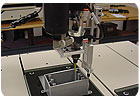
Automatic height measurement can be achieved in numerous ways, including laser triangulation, tactile sensors, ultrasonics and 3D stereoscopic vision.
Standoffs
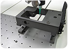
There are several ways to maintain a consistent dispense height with automated equipment. One of the simplest is a standoff. Commonly used for dispensing dots of material, standoffs are rarely used for dispensing gaskets. The reason is that the standoff can get in the way, especially when dispensing a closed-loop pattern, such as a circle.If this issue can be resolved, a standoff is the most consistent method of controlling dispense height. Often, the primary contributor to height variation while using a standoff is the finish at the end of the dispense tip. Beyond that, gasket height consistency is a function of how accurately the standoff is positioned in relation to the tip, as well as any compliance in the standoff during dispensing. As long as material flow is consistent, and the dispense path is free of debris and bumps, gasket height can be maintained to within ±12 microns.
Using a standoff also requires less cycle time than other height-control methods, which need a few extra seconds to measure the gap and position the dispense head. Since it’s strictly mechanical, a standoff requires no additional time.
There are two ways to resolve the crossover issue: rotate the standoff around the dispense tip, or rotate the part under the tip. Both have issues. Rotate the tip, and the dispense head becomes cumbersome. Rotate the part, and you’ll have to adjust speed and acceleration as the dispense path moves away from the center of rotation. As the size of the part exceeds 16 by 16 inches, inertia comes into play, which makes rotating the part impractical.
Programming a dispense path for a standoff-equipped machine can be complex. Ideally, CAD data is used to program the dispense path. However, CAD files are unlikely to include information on how the standoff is offset from the dispense tip. To solve this problem, the dispensing system must be able to translate XYZ CAD data to Y, Z and Q machine coordinates. At the least, it must be able to automatically calculate a Q value that corresponds to the direction of travel. It also must account for the distance of the dispense path from the center of rotation and adjust velocity and acceleration to compensate.
In the end, standoffs can solve dispensing problems related to part and fixture consistency, but they’re not a panacea. In fact, they can introduce new variables to worry about, such as foot cleanliness and maintaining the correct offset between the standoff and the tip. Engineers may find that a system with automatic height measurement may be worth the trade-off in cycle time.

Using a standoff to maintain a consistent dispense height requires less cycle time than other height-control methods.
Automatic Height Measurement
Automatic height measurement can be achieved in numerous ways, including laser triangulation, tactile sensors, ultrasonics and 3D stereoscopic vision. Regardless of technology, height measurement systems typically have two modes of operation.The pattern update mode provides a continual stream of data on the height of each part as it enters the system. As the machine measures the part, any distortion imparted by the fixture is cancelled out. If your parts are stable after molding or machining, you shouldn’t need this mode too often. If they’re not, this mode can be a solution, but it will add to cycle time.
The pattern run-time mode allows the machine to make global or local offset corrections. Frequently, these are simple Z-axis corrections. More effective are planar skew corrections, which can reset the plane of a part for best fit.
Height measurement data gathered by the system can be used for more than just adjusting the position of the dispense head. Engineers can use the data to monitor an upstream molding or machining process, or the system can measure key points to ensure the part has been correctly assembled. Is an insert in place? Is a spring mounted? Has a coating been applied? Indeed, just knowing that a part is present in the fixture is itself a benefit. Presenting an empty fixture to an automatic dispenser is a surefire recipe for downtime!
A complication of height measurement systems is the software necessary to make the most use of the data. Updating traditional 3D point cloud data becomes difficult for anything other than a general height offset. Applying skew accurately demands a motion control system that can address a matrix of X, Y, Z, Q, roll, pitch, yaw, velocity and acceleration. These operations, known as joint kinematics, serve to bring pallet and part coordinates into the machine’s positional frame of reference.
With both a tip calibration system and a height measurement system, dispensing equipment can obtain absolute rather than relative height measurements.
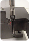
Tip Calibration
Anyone can eyeball the position of the dispense tip, but the alignment will be subjective. Actual measurements are much better. Like automated height measurement, automated tip calibration can be based on several technologies, including laser, tactile and vision sensors.Calibrating the end of the dispense tip eliminates a significant amount of tolerance stack-up. It cancels out positional error due to the tip, valve and even the axes to which they are attached! A tip calibration system applies an offset in X, Y and Z that is treated as a local offset. This offset is unaffected by part rotation or translation, or the shape of the tip.
In some cases, the calibration system can do double duty as a material detector. Once the tip is found, the end of the tip can be scanned for the presence or absence of material. This “feature” points out a potential drawback of many calibration technologies: Extraneous material at the end of the tip can throw off the results. If this becomes a problem, the tip should be wiped off prior to calibration, or an automated cleaning process can be built into the machine.
Automatic calibration solves the problem of misalignments related to changing tips or valve maintenance. It can also alert engineers to reduced or cutoff flow.

With accurate calibration and height measurement, it’s possible to dispense 51 microns above a substrate consistently.
Closing the Loop
With both a tip calibration system and a height measurement system, dispensing equipment can obtain absolute rather than relative height measurements. The problem with having just one or the other is that a relative offset must first be determined before any fluid can be dispensed. This is usually done with a gauge or a micrometer adjustment to the tip or the valve. The operator moves the tip to the first dispense point, lowers it using jog controls or a micrometer, and then raises it back up so the tip is traveling at the desired height above the part.If the system can calibrate both the height measurement gauge and the dispense tip, all the measurements can be absolutely pegged to the actual tip distance from the substrate. No other gauging is required. This tells the robot how high it is above the substrate. With accurate calibration and height measurement, it’s possible to dispense 51 microns above a substrate consistently.
In fact, the only limitation is the accuracy of the tip calibration system and the height measurement system. Because the height system tends to be the more accurate of the two, the ultimate limiter is the tip calibration system. Because of the complex motions required for calibration, the system will only be as accurate as the resolution and accuracy of the positioning platform.
Given the power of these sensors, fixtureless dispensing is now possible. With a vision system to provide information on part rotation and translation, and noncontact sensing to provide information on part height, dispensing programs can be dynamically adjusted to match a constrained set of circumstances. Fixture changeover, fixture maintenance and damage to parts loaded in and out of fixtures will become relics of the past.
While additional process control will add cost to dispensing equipment, it is a one-time cost, whereas gasketing materials are a recurring cost. For any project, engineers must consider the total cost of ownership. The key factors are initial machine cost, annual material cost, annual scrap losses and annual output. These four costs are linked in many subtle ways. Failure to evaluate them fully will result in excessive hardware expenditure, excessive material usage, or excessive cost overruns due to rework.
These are only a few tools that we have brought to bear on process variation in dispensing. And yet, they address more than half the problems we see in automated dispensing. If your dispensing process includes disposable tips, variation in fixtures and parts, and other shop floor realities, these tools will reduce operational headaches.
Height measurement data can be used for more than just adjusting the position of the dispense head. Engineers can use the data to monitor an upstream process, or the system can measure key points to ensure the part has been correctly assembled.
Closing the Loop Pays Off
Given a requirement for a round gasket 0.125 inch in diameter with an allowable variation of ±0.01 inch, what is the cost of accommodating the tolerance?It’s fair to assume that a gasket 0.115 inch in diameter will produce a seal within specification. Therefore, anything more than that is a cost overrun. A 0.115-inch bead has a cross section of 0.01039 square inches. A 0.125-inch bead has a cross section of 0.01227 square inches, or 18.1 percent more.
If the material costs $10 per cubic inch and the gasket is 14 inches long, then producing a gasket 0.125 inch in diameter will cost $1.71 per part. At an annual production volume of 100,000 parts, an assembler will spend $1,710 per year on gasketing material. At an annual production volume of 1 million parts, the material will cost $17,100 per year.
If the dispensing process allowed the gasket to vary by only 0.0005 inch in height, and a set point was chosen that provided a bit of a buffer (say, 0.116 inch instead of 0.115 inch), the savings would realistically be 1.546 cents per part. At high volumes, a 14 percent savings in material can be significant.
We have not factored in that these methods also reduce rejects. Every rejected gasket is material lost and potentially can represent a lost part, as well.
Lesson Learned
Over the years, we all learn a few lessons taught at great expense! Here’s one I learned about FIP gaskets.Often, a prototype assembly is built using O-ring cord stock as a gasket. When the prototype progresses to full production, the O-ring is converted to a FIP gasket without any thought to the implications of the switch. Invariably, this produces a poor performing, very expensive gasket.
Unfortunately, many designs surround gaskets with vertical walls or standoffs. These are necessary to prevent overcompression of the gasket. However, if the walls are too close together, two problems arise: wetting to the walls and shear-induced delamination. When the FIP material wets to the walls, additional area is occupied by the gasket. When the product is assembled, a shear component is applied to the gasket that is parallel to the clamping force. This can cause the gasket to separate at the wall or even rip.
An ideal design will have walls that are sufficiently offset from the gasket to prevent wetting. A FIP gasket is a solid. When squeezed, the gasket must be able to extrude somewhere. For a gasket with a wall on both sides, the area between the walls, minus any intruding boss, must be more than the cross section of the gasket itself.
It’s possible to estimate what an optimal design might look like. However, given the number of variables involved, actual testing is crucial for nailing down the design of the seal face. Running a few simple calculations beforehand will certainly reduce iterations of the design cycle.