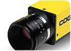
Today’s color vision tools are cost-effective enough to use
during the early stages of production. Photo courtesy Cognex Corp.
A single misplaced wire in an air bag sensor connector has the potential to cause a fatality, so it’s critical that the connector is assembled correctly. Automated visual inspection systems can verify that the right color wire is attached to each connector.
In years past, this type of inspection would have been expensive, due to the difficulty of writing color inspection algorithms that can distinguish between different shades of the same color. Today, however, color vision tools can distinguish between shades, greatly reducing the time required to program a vision system and making it cost-effective enough to use during the early stages of production.
One connector manufacturer has begun using color vision systems to inspect its new line of products specifically designed for automobile air bag sensors. The product line includes many different connectors for different makes and models of automobiles.
Each connector has four contacts, and each contact has a wire connected to it. Each wire has a spiral of one color arrayed against a background color, such as blue on white or red on green. The color vision systems make sure that the right color wires are attached to the contacts.
Before installing the color vision systems, the company had operators assemble new products with hand tools. They would then manually inspect the connectors. Operators were normally very good at inspecting parts, but they had a tendency to become distracted, especially near the end of their shifts as they got tired. The potential for a bad air bag sensor connector slipping through to a customer was always a concern.
This led the manufacturer to seek machine vision systems that could inspect the connector while it was produced manually. The manufacturer decided to perform five inspection operations on each connector using three Cognex vision systems: two In-Sight Micro 1100C systems and one In-Sight1403C system.
Initial testing showed the vision systems were 100 percent effective in detecting problems with the air bag sensor connectors. The manufacturer then had the vision systems installed on two manual-production lines. AVI Inc., a vision integrator based in North Little Rock, AR, did the installation and used In-Sight Explorer software to develop the application.
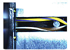
Wires are fixtured for color inspection. Both the primary
color and stripe are inspected to be sure they are the proper color and in the
proper position. Photo courtesy Cognex Corp.
System Capabilities
The 1100C color vision system provides a standard 640 by 480 resolution, while the 1403C offers 1,600 by 1,200 resolution and a faster processor. Both systems feature a very small camera, which measures just 30 millimeters by 30 millimeters by 60 millimeters, weighs 5.1 ounces and can fit in the palm of your hand.The vision systems offer a nonlinear calibration tool that lets users mount the camera at angles of up to 45 degrees. This gives users the flexibility to mount the camera in tight spaces on robots and hard-to-reach machinery anywhere on the production line.
Each system also includes a vision tool library that lets users handle a broad range of vision applications. Key vision tools used by the connector manufacturer are PatMax, Color Match, Color Extract and InspectEdge.
If a vision system can’t repeatedly locate parts because of wide variations in part orientation, size and appearance, then vision yield and reliability will be significantly reduced. These variations include part contrast, multiple parts, changes in lighting, image focus, degraded appearance and partially hidden parts. PatMax utilizes advanced geometric pattern matching technology to reliably and accurately locate parts. PatMax also can significantly reduce or eliminate fixturing requirements and cost.
Color Match is a high-speed color sortation tool that uses 24-bit color resolution to reliably distinguish between small variations in hue. Color Extract enables users to ensure a robust color model definition by providing feedback with color swatches, image marking and slider adjustments.
InspectEdge verifies the correct assembly of components, straight or circular, and finds flaws in part appearance. It also finds deviations in edge position, as well as defects and gaps with position and width. This tool provides repeatable inspection results despite changes in part orientation.
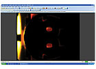
The 1403C camera inspects for the presence of four
red dots that indicate the connector has been assembled correctly. If the
connector has not been assembled correctly, holes will appear instead of the
red dots. Photo courtesy Cognex Corp.
How It Works
The vision systems used by the manufacturer are controlled by an Omron PLC, which is directly connected to one 1100C. This 1100C is connected to the 1403C by an Ethernet cable.When a part is placed in the fixture, the PLC sends a signal to the In-Sight 1100C vision system to inspect the wires on the connector. The vision system uses hue, saturation and luminescence to make sure the correct color wire is attached.
Rick Farrer, president of AVI, set up the application without having to write a single line of code. To train the vision system to recognize a particular part number, Farrer first acquired an image of that part. Then he selected the area around one wire and used the software’s Color Match tool to detect both colors that are supposed to be in the wire.
It only took a couple of minutes for Farrer to configure the vision system to inspect all four wires for each product number. In fact, the process is simple enough that the connector manufacturer’s maintenance technicians have taken over the task of programming the vision system for new part numbers.
After the 1100C camera inspects the wires, it signals the higher-resolution 1403C camera to turn on a backlight that lights up gaps between contacts in the female connectors and acquire an image. The four female contacts create two gaps whose size needs to be held to 2 microns.
Blob tools locate the two gaps by detecting large light-colored objects. Then, based on the location of the blobs, edge tools precisely measure the location of the contact on each side of the gap. The vision system then measures the gap by determining the distance between the connector edges and the contact.
Next, the 1403C camera inspects for the presence of four red dots that indicate that the connector has been assembled correctly. If the connector has not been assembled correctly, holes will appear instead of the red dots.
For correctly assembled connectors, the second In-Sight 1100C camera triggers a light that shines in from the side of the part, and Color Extract and Color Match tools look for the dot. Next, the 1403C uses another Color Extract and Color Match tool to look for a black dot on the connector that verifies it passed electrical testing. Finally, the PatMax pattern matching tool examines the housing to verify that the latch on the connector is in the correct position and the correct latch was used. Color Extract and Color Match tools verify the color of the latch.
When the tests are completed, the 1403C sends the results back to the 1100C vision system. The 1100C then sends the results, including the dimensions of the contact gap, to an operations control server and also signals the PLC that the inspection operation has been completed and whether the part has passed or failed.
The effectiveness of the vision systems on the manual-assembly lines convinced the manufacturer to install a similar setup for an automated line to produce the connectors. AVI Inc. again did the installation and used In-Sight Explorer software to develop the application.
ASSEMBLY ONLINE
For more information on vision systems, be sure to read the following articles: