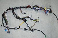
When watching an operator test an automotive wire harness, one is reminded of old-time photos and TV skits about telephone switchboard operators of the 1950s and 1960s. They were able to plug and pull cords into and out of jacks quickly and accurately.
Today’s test operators are just as fast. Partly this is due to the high volume of wire harnesses Tier 1 and Tier 2 suppliers must assemble and test on a daily basis.
But, just as important are the testers operators rely on. These technologically advanced machines can perform a continuity, hipot or component-specific test within just a few seconds.
“The sheer volume of harnesses needed globally every year is incredible when you do the math,” says Brent Stringham, director of business development for Cirris Systems Corp. “Worldwide, more than 50 million vehicles are produced annually, and on average, each vehicle has about 20 wire harnesses. That equates to some 1 billion harnesses over the course of a year, or nearly 4 million each day. It’s no surprise suppliers need fast and reliable testers to maintain high production volumes.”
Continuity of History
Automobiles have always had some level of wiring, but initially manufacturers emphasized troubleshooting rather than testing. That changed by the 1930s, as wiring harnesses became more complex.
Wires were tested with a manual go—no-go light system, explains Eric Harter, product manager for Dynalab Test Systems Inc. “The two points of a wire were run through a light bulb for continuity,” says Harter. “If the light came on, it meant current was flowing and the wire was good.”
By the 1950s, harness manufacturers began using telephone stepper switches (relays) to continuity test each harness wire and verify its location in a connector. Testing was fairly slow, and remained so for many years as automobiles required larger harnesses to power windows, seats and other standard features.
When electronic switches began being used in testers in the late 1980s, the speed of continuity testing increased significantly. It has gotten exponentially faster over the past 25 years. For example, today’s standard tester can test 1,000 wire points in 3 seconds, whereas a 1990s tester needed 60 seconds.
Despite the increase in testing speed, the continuity testing process has remained unchanged for several decades. The tester is located on either a harness board, test table or standard table. Manufacturers that use a board test harnesses as they’re being built. A test table features a series of connector blocks (also called tiles) that serve as the mating fixture. When testing simple harnesses, it’s economical to use a standard table and stand-alone tester.
The operator sets the tester to a specified low voltage (5 to 15 volts) and resistance threshold (in ohms), connects it to a mating fixture, and plugs all harness connectors into the mating fixture. The tester runs continuously.
Within fractions of a second, it generates and applies current to all wire test points in a specific sequence. Test results appear on the display panel. If no fault is detected, a pass is displayed, accompanied by a tone. When a fault is detected, the tester stops. It displays the connector and pin numbers, and indicates if the problem is a short or open circuit. A short circuit occurs when too much current flows through wire, an open when current flow stops due to high resistance.
The display stays on and prevents further testing until the problem is resolved. PC-based testers display this information on a computer monitor, often with pictures of the affected connectors.
Some low-voltage testers only perform continuity testing. Others have the capability to detect and actuate harness components, including relays, switches, sensors, capacitors, resistors, connectors and diodes.
High-voltage testers are often used for hipot (high potential) and isolationresistance testing. In a hipot test, 1,000 or more volts (direct current) is applied to all test points to see whether or not current flows from one point to another. If no current flows, the test points are properly isolated. Isolationresistance testing tests the quality of wire insulation.
Some Test(er) Questions to Answer
Before purchasing any tester, a harness manufacturer needs to find out the tester’s capabilities. The most important are voltage, ohms, and component tests the tester can perform. Harness makers also need to consider data logging and traceability. Many testers feature a controller that enables an operator to save and share test data on networks.
“To generate test programs, the tester needs to be able to import and process data,” says Kjell Uddeborg, senior software engineer for Cablescan Inc. “If it can’t import data directly, find out how much work will be required to convert the data to a format that can be imported.”
For example, Harter says the tester software needs to be able to convert drawings made in CAD or software programs like Capital H and VeSys (from Mentor Graphics Corp.). The tester’s HMI also should be userfriendly so operators can easily create, save and recall test programs.
Cost is just as important as capability, according to Stringham, but must be considered in light of harness complexity and the tests required by the OEM. For example, a basic continuity tester that costs several hundred dollars may be adequate for high-volume manufacturers of simple harnesses. But, an advanced tester that costs several thousand dollars may be required for more complex harnesses, such as those that transmit power to various sections of the engine, or those used in the complex computer systems in today’s vehicles.
A final factor to consider is available space. Juan Perezchica, key account manager for TSK Prufsysteme GmbH, a Komax Group company, says this is primarily a concern for manufacturers that require one or more test tables. TSK makes custom test tables that can be quite large. They feature 1.2-metersquare sections that are joined to form vertical or L-shaped configurations.
The Latest and Greatest
All three models in Dynalab’s NX series (Solo, Pro and Pro+) are lowvoltage testers designed for continuity and other tests, such as active testing of relays in a harness. The relay is inserted into an output module accessory, which is connected to the tester and serves as the mating fixture. A low-voltage current is then introduced to energize the relay.
“This process enables a manufacturer to measure continuity change of the harness when the relay is active,” explains Harter. “It also serves as a simple functional test of the relay.”
The NX testers can also perform high-speed testing for shorts, and they can be used for testing diodes, resistors and capacitors. Built for industrial environments, the stand-alone modular testers feature a simple four-button user interface and a four-line screen that displays default or custom messages with accompanying sounds.
The NX Solo tests up to 256 points, the Pro up to 512 and the Pro+ up to 32,768. The Pro and Pro+ are the same tester, but the Pro+ can be connected with up to 32 expansion units (each handles 1,024 points) using 2- or 6-foot cables. Both models have 1.3 megabytes of memory capacity for test-program storage.
Uddeborg says manufacturers use Cablescan testers to test automotive harnesses at all stages of production, as well as prototype testing and fieldreturn analysis.
TestMate, one of the company’s continuity testers, tests up to 256 points with an expansion unit. Its universal mating fixture accepts interface cards for many types of connectors. Test programs are created and assigned signature codes from known-good harnesses.
The Series 90HV-S23 is a PC-based tester that performs low-voltage and high-voltage testing. It uses solid-state devices to perform continuity testing and to test diodes, switches, capacitors and resistors. However, the tester uses relays for high-voltage isolation testing and high-current continuity testing, which tests the quality of harness connections (solder and crimp terminations). Relays in the unit under test can be activated and tested in the energized or unenergized position.
The tester tests up to 1,472 points by itself or 47,104 points with 32 expansion cabinets, which can be interconnected within 200 feet. Continuity and resistance- isolation thresholds can be set as system defaults, for individual programs or while running specific tests.
Test programs are created by importing net lists from CAD stations or scanning known-good harnesses. A full-function program editor provides wire list programming through the keyboard when CAD data or a knowngood harness is not available. The editor can also change test parameters and existing programs.
Delphi Automotive PLC, the worldwide automotive parts manufacturer, has been testing complex harnesses with Cirris Signature Easy Touch since 2012. These harnesses control dashboard functions, blind-spot lights mirror movement, antennas and other complex systems in the car.
The tester also performs standard hipot, high-speed hipot and highvoltage insulation-resistance testing. The unit tests wires (including twisted pairs) for opens, shorts, and miswires. It measures 17.5 by 9 by 5 inches, and features a 10.4-inch touchscreen and an integrated PC that runs Windows 7. A VGA output and USB ports enable operators to plug in an external monitor and keyboard.
Like the Easy Touch, the 1100R+ continuity tester is small and versatile. More than 200 standard adapters can plug directly into the tester, eliminating the need for adapter cables. In addition, its 128-test-point capability can be increased to 1,024 by linking it with seven expansion boxes.
The tester has a resistance range from 0.005 ohm to 100,000 ohms and a scanning rate of 128 points per 0.25 second. CTL-Win software enables the operator to control the tester from a PC, as well as create, edit and save test programs.
Although customized, all TSK test benches feature CS WIN nx software and a CT series (CT11, CT12, CT30i, CT35) tester. The software’s TSK Studio is the control centre for all electrical, module and vision tests. Its clear layout allows fast and direct access to the most frequently used functions.
Equally important, the software features a Multi-Window editor that simplifies programming and allows simultaneous operation of various testing programs. The software enables operators to import testing programs and connector libraries, and it also features an ActiveX interface so users can easily transfer content to and from Excel spreadsheets.
Besides standard wire, the low-voltage (0.1 to 15 volts) CT35 tests optical fibers and standard harness components for continuity, function and short circuits. It transfers data to an attached PC via Ethernet, and displays pin numbers in error messages on the computer screen. The company also offers vision test systems, which rely on color, optical character and pattern recognition to validate the presence and correct position of fuse boxes and relay carriers in harnesses. Height control is used to validate whether fuses and relays are correctly inserted.
Scanning of boxes and carriers is done by a camera built into either a table, stand-alone unit or mobile workstation. Related objects are also inspected, including fuses, screws and bolts, connector-locking mechanisms, label inscriptions and unicolor wire. Vision testing takes place either during preshipment loading, harness mounting or final automobile inspection.


