By all accounts, the latest mission of the space shuttle Discovery in July was a success. Before the launch, however, some engineers argued that the shuttle should not have taken off at all.
Engineers from the Aerospace Corp. (El Segundo, CA), a federally funded, independent research firm set up to advise NASA and the Air Force, raised concerns that some electronic assemblies in the shuttle's flight control system could fail due to shorts caused by tin whiskers. NASA managers countered that the risk from tin whiskers was minimal or nonexistent. Moreover, they argued, the assemblies in question were backed up by redundant systems. The flight would go ahead as planned.
Debate over the dangers, causes and cures for tin whiskers is not confined to NASA mission control. Although electronics assemblers have been wrestling with lead-free solder for nearly 10 years now, the issue of tin whiskers continues to be, well, a prickly one. Despite years of research, engineers have yet to reach clear consensus on:
- the underlying chemical mechanism behind tin whiskers.
- the key factors that promote their growth.
- ways to keep them from growing.
- tests to determine the propensity of whiskers to grow on a surface.
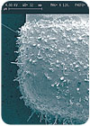
Tin whiskers are electrically conductive, individual crystals of tin that grow spontaneously from pure plated tin. The phenomenon was first reported in electronic assemblies in 1946, but it has only emerged as a significant problem within the past decade, as assemblers converted to lead-free solder. That's because even trace amounts of lead in tin are enough to prevent whiskers from growing.
The diameter of tin whiskers ranges from 0.3 to 10 microns, and they can exceed 1.5 millimeters in length. They can be straight, bent, kinked or forked. They are usually solid, but some can be hollow.
"The growth rate for tin whiskers is unknown," says Guna S. Selvaduray, Ph.D., professor of materials engineering at San Jose State University (San Jose, CA). "They can start to grow soon after plating, or they can lie dormant for years."
Tin whiskers cause two reliability concerns with electronic assemblies. The most common is short circuits. Whiskers can cause both stable and transient shorts, and they can also cause plasma arcing in a vacuum. Individual whiskers can carry a current of 75 milliamperes before fusing. In space, a plasma of tin ions can sustain several hundred amperes.
The other reliability concern is mechanical. The fine crystals can break off and interfere with mechanical assemblies.
Since 1992, tin whiskers have been blamed for the complete failure of three commercial satellites and the partial disabling of four others. Whisker-related failures have also been reported in pacemakers, missiles, aircraft radar systems, and electrical relays at a nuclear power plant.
Causes and Risk Factors
Tin whiskers can grow from both electroplated tin and immersion tin coatings. Any electroplated tin coating is susceptible to whisker growth, but bright tin finishes are more prone to whiskering than matte or satin tin finishes.
Compressive stress is believed to be the driving force for whisker formation. Engineers theorize that whiskers are pushed out as the tin deposit tries to relieve stress through recrystallization and grain growth.
Compressive stress can come from internal or external sources. Internal sources include residual stress from the plating process; the formation of intermetallic compounds within the boundaries of the tin grains; or differences in thermal expansion rates between the tin plating and the copper substrate. External sources include bending, stretching or scratching of the surface after plating, or the installation of threaded fasteners.
"If parts have pure tin finishes, engineers should be especially careful to avoid mechanical damage to tin-plated surfaces," advises Michael Osterman, Ph.D., director of the Electronic Products and Systems Consortium at the Center for Advanced Life Cycle Engineering at the University of Maryland (College Park, MD).
The thickness of the plating seems to make a difference in whisker formation. Whiskers are more likely to form in plating between 1 and 20 microns thick. They are less likely in plating less than 1 micron thick or more than 20 microns thick.
Either way, a well-controlled plating process is essential for reducing the risk of whisker formation. Process parameters that lead to whisker formation include high current densities, low temperatures, and excessive amounts of brightener in the plating bath.
"Tin whiskers grow faster in tin plating with a small grain size," says Selvaduray. "The grain angle can also affect the growth rate."
One problem with preventing tin whiskers is that they can grow in a variety of environmental conditions. They can grow in atmospheric pressure or in a vacuum. They can grow in dry or humid conditions. They can grow with or without an electrical field. They can develop at any temperature, but grow best at temperatures from 20 to 75 C.
Preventing the Problem
Because the formation of intermetallic compounds between the copper substrate and the tin plating has been linked to whiskers, some engineers have suggested that placing a thin layer of a less reactive metal, such as nickel, between the two metals will reduce the likelihood of whisker growth. However, this strategy has shown mixed results so far.
At the APEX conference in February, Chen Xu and a team of engineers from Enthone Inc. (Jersey City, NJ) reported good results with a layer of nickel 1.5 to 2 microns thick, particularly if the tin plating was very thin. The researchers examined tin plating in two thicknesses: 3 microns and 10 microns. With the nickel barrier, the layer of tin 3 microns thick produced significantly less whiskering than the layer of tin 10 microns thick. Without the nickel barrier, however, the results were the opposite. The 10-micron-thick plating exhibited significantly fewer whiskers than the 3-micron-thick plating.
"This contrast can be understood if one looks at the difference in interfacial reactions between tin and copper, and tin and nickel," explains Xu. "At both interfaces, there is significant intermetallic formation, as well as interdiffusion. However, tin is the slow-diffusing species at the tin-copper interface, while it is the fast-diffusing species at the tin-nickel interface. With tin over copper, more copper is diffusing into the tin than there is tin diffusing into the copper, which leads to excessive material in the tin layer. With tin over nickel, tin diffuses faster into nickel than nickel into tin, which results in a material deficiency in the tin layer. The difference leads to compressive stress in the tin-copper interface, but tensile stress in the tin-nickel interface."
Another possible strategy for preventing whiskers is to heat freshly plated circuit boards enough to reflow the tin. This is thought to increase the size of the tin grains and eliminate any internal stress caused by the plating process. However, this strategy has also shown mixed results, and it may compromise the solderability of the board.
For similar reasons, annealing freshly plated boards has also been tried. Besides relieving stress from the plating process, annealing may promote better, more uniform growth of intermetallic compound between the tin plating and the copper substrate. This technique has shown promise, but more studies need to be done to determine the ideal temperature, baking time, heating rate and cooling rate. In addition, there's no evidence to suggest that it can prevent whisker growth in the long term.
While some engineers try to prevent whiskers by addressing their underlying growth mechanisms, others hope to impede their advance by putting something in their way-a conformal coating or an encapsulating foam. Unfortunately, this strategy, too, has proven less than successful.
In 2005, for example, engineers at the Boeing Co.'s Phantom Works (Seal Beach, CA) reported on their study of conformal coatings for suppressing tin whiskers. Six coatings were tested: three UV-cured urethane-acrylic hybrids, a silicone, a non-crosslinked acrylic, and Parylene C, a highly crystalline vacuum-deposited polymer.
The coatings were applied to tin-plated brass coupons. Each coating was applied in thicknesses of 1 mil and 3 mils, except for the Parylene, which was applied at a uniform thickness of 0.4 to 0.5 mil. The coupons were then aged for more than 2 years. The coupons were left for 401 days under ambient temperature and humidity. They then spent 347 days at 25 C and 97 percent relative humidity.
In the end, all the coatings were eventually penetrated by tin whiskers. Under ambient conditions, five of the coatings had nodules growing beneath them, but none were penetrated by whiskers. The Parylene coupons showed no growths of any kind under the coating.
After aging in humid conditions, all the coatings were penetrated by whiskers. The non-crosslinked acrylic coating showed the most penetrations, while one of the UV-cured urethanes had the fewest.
"The high humidity...facilitated penetration of the coatings either by promoting growth of larger whiskers or by changing the properties of the conformal coatings so that they became easier to penetrate," explains Boeing engineer and lead author of the study, Thomas A. Woodrow, Ph.D. "[However] all the coatings suppressed the formation of tin whiskers when compared to the uncoated control samples."
The researchers found no obvious relationship between the physical properties of the coatings and their ability to suppress whisker growth. However, the thickness of the coating did make a difference. Whiskers were found more frequently at thin spots in each coating thickness.
Sidebar: What's in Your Boards?
Visually, it's difficult, if not impossible, to tell the difference between an electronic component or circuit board that contains lead and one that has not.
This is no trifling matter. If a lead-bearing component is inadvertently used in a lead-free assembly, it may be unable to withstand the high temperatures needed to reflow lead-free solder. More importantly, it could put the manufacturer at risk of violating the European Union's Restrictions on the Use of Hazardous Substances (ROHS), which went into effect in July.
Conversely, if a lead-free component is inadvertently used in a circuit board built with a traditional tin-lead solder and finish, the assembly could develop tin whiskers. In addition, because the lead-free component will not reach the required reflow temperature, a good solder joint will not be created.
The latter case is exactly what happened recently to a major manufacturer of telecommunications equipment. The manufacturer runs six electronics assembly lines. Five are dedicated to lead-free assembly; the sixth is reserved for high-reliability assemblies requiring traditional tin-lead solder. Somehow, lead-free ball grid arrays accidentally found their way into a batch of tin-lead assemblies.
"The lead-free BGAs needed to be reflowed at 250 to 260 C, but the tin-lead boards only had to be heated to 220 C," recalls Drew Hession-Kunz, vice president for business development at Innov-X Systems (Woburn, MA). "As a result, the BGAs initially adhered to the boards, but they did not stay on. When they got into the field, they started popping off."
The telecom manufacturer might have avoided the problem if assemblers had the ability to determine instantly whether or not the BGAs contained lead. The Alpha handheld X-ray fluorometer from Innov-X Systems does just that.
The pistol-grip fluorometer weighs approximately 3 pounds. When the operator points the device at an object and presses the trigger, it emits a short burst of X-rays with approximately 1 percent the energy of a dental X-ray. Each element in the object absorbs the X-rays and re-emits them in a unique wavelength pattern. The fluorometer detects these incoming X-rays and reports what elements are present in the sample area, and in what concentrations.
"A library of hundreds of solder alloys is stored in the device, so it can tell in an instant if it's looking at [tin-silver-copper] 305, for example," says Hession-Kunz.
For more information on handheld fluorometers, visit www.innovxsys.com or call Innov-X Systems at 781-938-500.

