Solving Leak Testing Challenges
When we asked suppliers of leak testing equipment to tell us their most challenging applications, we received dozens of reports on everything from diesel engines to water softeners.
 Leak testing of one form or another is used to check the integrity and functionality of a wide range of assemblies, from catheters and coffeemakers to fuel rails and fire extinguishers. Some applications are easy. Others need some finagling. As the following reports show, suppliers of leak testing equipment find innovative ways to solve the toughest testing challenges.
Checking Check Valves
The difficulty of disposable medical products is that they must be produced relatively inexpensively in high volumes, and yet they must also meet strict quality standards.
Recently, a systems integrator contacted InterTech Development Co. (Skokie, IL) to supply test equipment for a machine assembling small check valves for a medical device. The valves needed two leak tests and a function test, with the machine indexing eight check valves to the test equipment every 2 seconds.
InterTech provided two Model 1075 pressure-decay leak detectors to perform the three tests-a leak test at 220 inches of water column, a leak test at 5 inches of water column, and a forward direction test, or cracking pressure test, at 50 inches of water column to determine if the check valves closed appropriately.
One challenge was to create a station that could test eight parts simultaneously without taking up too much real estate on the assembly machine and without adversely affecting efficiency and productivity. A four-channel instrument, the Model 1075 could handle the volume requirements and still fit within the space constraints of the system. Each channel can operate independently or synchronously, depending on the testing criteria. Using two, four-channel instruments is significantly less expensive than eight one-channel instruments or four two-channel instruments.
Another tricky aspect of this application was the leak test at 5 inches of water column, which is an especially challenging pressure to maintain.
The leak detectors’ 24-bit, high-resolution convertors, which can detect minute pressure losses, were a critical factor in meeting the cycle time requirement of 0.8 second. Additionally, the integrator minimized the test circuit volume, so less time is needed to pressurize the valves.
A special feature of the system is the variety of connectivity options it provides, including Ethernet and RS-232 communications. Ethernet connectivity allows engineers to communicate with the leak detector through a web browser. That enables engineers to view diagnostics and troubleshooting options, as well as access on-line reference manuals. The leak detector also has a USB port, so engineers can attach additional instruments or download test results and programs.
For more information, visit InterTech at www.intertechdevelopment.com or call 847-679-3377.
When the beads become saturated with minerals, they must be regenerated with sodium. So, brine from the second tank is periodically pumped through the beads, which grab the sodium and give up their minerals. This mineralized water goes down the drain.
All this water flow is governed by a cam-actuated valve manifold made from plastic. Needless to say, the manifold can neither leak nor occlude the flow of water. That’s where Forward Technology (Cokato, MN) comes in. The company makes a variety of equipment for joining plastic parts, including ultrasonic, hot-plate and spin-welding machines. It also supplies equipment to check plastic assemblies for leaks and flow.
Recently, a water softener manufacturer asked Forward Technology to provide equipment to assemble and test a valve manifold. Designing a machine to assemble the manifold was relatively easy. Designing a machine to test the assembly for leaks and flow was tricky.
The manifold requires four checks: two pressure-decay leak tests, a flow test, and a vacuum test. During the test process, different valves in the manifold must open or close in a specific sequence. An operator could do this manually, but this would make the test process labor-intensive and error-prone. Forward’s engineers devised a way to open and close the valves automatically, using small linear actuators.
Coordinating the activity of testers and actuators is “the sort of thing we do really well, since we specialize in PLC-based test systems,” says Andrew Tapper, engineering manager for Forward Technology. “A standard, out-of-the-box leak tester typically can’t handle all that extra automation.”
Measuring 12 by 6 by 8 inches, the manifold is assembled with multiple hot-plate welds. After assembly, the manifold is manually loaded into the test station. When the machine is actuated, it inserts a series of plugs into the assembly, and the leak, flow and vacuum tests are performed automatically using ordinary air. “If any test fails, the machine pauses for the operator to take corrective action, either restarting a test or removing the faulty part,” says Tapper.
If the manifold passes all the tests, the machine automatically marks the part with a code. The entire process takes just under a minute.
For more information, call Forward Technology at 320-286-2578 or visit www.forwardtech.com.
Recently, a manufacturer of fuel rails contacted Alcatel Vacuum Products (Hingham, MA) to provide a leak-detection technique that was at least one order more sensitive than the pressure decay method. The system needed to have simple tooling, and it had to be more tolerant of background contamination than helium mass spectrometry. In addition, the new system had to be faster-or at least no slower-than the current testing method.
The manufacturer needed to test a fuel rail with a leak specification of 0.5 cc per minute at 72 psig. Because the part would be tested after brazing, it could be warm during testing, so the new system had to tolerate temperature changes in the part.
The solution was a leak detector that uses diluted hydrogen as the tracer gas-the H2000 Plus with an AP29 active probe. Diluted hydrogen (95 percent nitrogen, 5 percent hydrogen) is nonflammable, environmentally friendly and readily available. The leak detector is equipped with gas-field effect transistors (GAS-FET) that can detect leak rates as small as 5 x 10⁻⁷ cc per second.
To start the process, openings in the fuel rail are sealed, and the assembly is positioned in a simple chamber designed to work at atmospheric conditions. Closing the chamber initiates an automatic test cycle. Because the test is done under atmospheric conditions, the seals and materials for the part and chamber are not critical.
Once the rail is pressurized to 72 psig with the test gas, it sits for a short time to allow any leaking gas to accumulate in the chamber. During the accumulation time, the air inside the chamber is circulated with a fan. Next, the system draws an air sample from the chamber, analyzes it, and issues a pass-fail indication based on a preset alarm point. When the test is over, the system vents the gas from the component.
For more information, call Alcatel Vacuum Products Inc. at 781-331-4200 or visit www.adixen-usa.com.

Fastest Inc. (Roseville, MN) makes connectors for transferring liquids and gases, such as helium, propane and refrigerants, to and from assemblies. Leak testing is a major application for the company’s products.
Recently, a manufacturer of large diesel engines contacted Fastest for help with a leak testing challenge. Because of more stringent emissions laws, exhaust gases from a diesel engine must pass through a filter before reaching the air. The engine maker had to test the large, cylindrical manifold leading to the filter for leaks. The challenge was the size of the opening that had to be sealed for the test: It was approximately 6 inches in diameter.
Initially, the engine maker used a simple cam-over plug to seal the manifold. This device uses a lever-operated cam-and-pawl mechanism to create the seal. Though simple and inexpensive, cam-over plugs have some limitations, explains Mark Spindler, customer service manager at Fastest. Because the elastomer seal takes a compression set quickly, the plug loses effectiveness over time, especially with large-diameter holes. To compensate for this set, the connectors require manual adjustments to increase compression on the seal. As a result, getting consistent test results can be difficult. Finally, bumping the lever can cause the connector to accidentally pop off, putting operators at risk of injury.
The FIG connector from Fastest proved to be a better alternative. The connector grips and seals rough, cast parts and out-of-round ports with external beads, which are common on manifolds. The FIG mechanically grips the bead. Then, using shop air at 60 to 90 psi, a pneumatically operated elastomer seal compresses into the inside diameter of the part to provide a leak-tight connection. The internal seal is activated by a piston, which expands an elastomeric material-either neoprene or urethane-to form a leak-tight connection. Testing, filling or flushing the piece is accomplished by introducing air, liquid or gas through the connector port.
Because the connector is pneumatically actuated, rather than mechanically actuated, no operator adjustment is needed. In addition, the gripping feature on the connector is less vulnerable to accidental disengagement than a lever, minimizing risk to the operator. As a result, the engine maker’s leak testing process is both safer and more accurate.
Fastest developed the FIG connector specifically for the engine-testing application. Previously, the company had only offered a 4-inch connector. Increasing the size of the connector to 6 inches required more than just changing a few dimensions, explains Spindler. Fastest’s engineers knew that, as the size of the connector increased, the forces from operating pressure and test pressure would increase exponentially. If such forces were unbalanced, it could lead to seal extrusion or displacement. Unbalanced forces and seal containment had to be carefully analyzed to ensure that the connector would work as intended.
For more information, visit www.fastestinc.com or call Fastest at 800-444-2373.
However, as a manufacturer of transmissions for trucks and off-road vehicles recently learned, setting a sound specification for leak tightness is critical for establishing a leak testing process that is both reliable and cost-effective.
Truck transmissions are large, complex assemblies that are challenging for any leak testing technology. Housed in complex metal castings, they must be checked for both internal and external leaks. The problem with castings is porosity-tiny bubbles in the metal caused by internal shrinkage, gas cavitation, oxide films and inclusions. These small voids are often invisible, but they nevertheless provide a way for fluids or gases to escape. Needing a reliable leak test strategy, the transmission maker turned to Advanced Test Concepts Inc. (ATC, Indianapolis) for help.
The first step was to set meaningful leak tightness specifications for the components and the final assembly. When setting such specifications, ATC recommends an approach called equivalent microgeometry (EMG). The EMG is the largest, single flow path for leaks that can be tolerated in an assembly. For the truck transmission, the EMG represents the widest pinhole that will not leak transmission fluid. Anything larger will leak transmission fluid at operating conditions.
The EMG approach is generic and independent of the method used to leak test the assembly, explains Hemi Sagi, director of ATC. Although the flow rate of air or a tracer gas can be correlated to flow path geometry for leaks, these correlations are often oversimplified, resulting in leak tightness specifications that are too strict or too lax.
Lab tests conducted by ATC and dynamometer tests conducted by the transmission manufacturer established the EMG for the high- and low-pressure oil cavities in the transmission.
In the end, the transmission manufacturer set a tighter leak specification for individual components of the transmission than for the final assembly. That’s because the goal for testing the components is to check for porosity in the castings and defects in the sealing surfaces, whereas the purpose of testing the final assembly it is to find assembly errors and missing or defective seals.
The leak specification for the components was tight, so the fixture and seals had to be carefully designed. Furthermore, the functional seal line of the components had to be part of the test, so defects in the sealing surfaces could be detected.
ATC’s Model E leak test instrument was used to test the components, while the Model IPE was used to test the fully assembled transmissions. Both instruments were equipped with ATC’s microflow sensor, the Intelligent Gas Leak Sensor (IGLS). Using air, the IGLS can detect small leaks that are typically require helium mass spectrometry to measure.
Given the large test volume (15 gallons or more) and short cycle time (approximately 60 seconds) for the assembled transmission, a stable sensor was needed to ensure consistent results from day to day. In addition, the test instruments had to be flexible, because the test volume varied depending on the transmission model.
Engineers performed numerous tests to optimize the parameters. An optimum test circuit was developed to ensure a stable and quick-charging process with the ability to detect leak rates in the range of 10 cc per minute at approximately 10 psig.
For more information, call ATC at 317-328-8492 or visit www.atcinc.net.
Thus, a manufacturer of heavy-duty hydraulic components wanted to leak test a critical circuit joint before any more value could be added to the assembly. The joint consisted of two metal fittings and a gasket or O-ring. The diameter of the fittings ranged from 1 to 5 inches. The assembly could not leak more than one drop of hydraulic fluid over a three-year period, despite high temperature conditions and operating pressures of more than 2,000 psig.
The Protec P3000 helium leak detector from Inficon (East Syracuse, NY) handled the job. The P3000 is a sniffer-style leak detector. To run a test, the assembly is pressurized with helium. Then, an operator scans each joint with a sniffer probe, which inhales gas at a high rate. Inside the leak detector, finely tuned sensors identify abnormal amounts of helium. The amount of helium in the gas load corresponds with the leak rate.
As with any leak testing application, the key challenge was correlating a leak rate for helium with the manufacturer’s maximum leak specification for hydraulic fluid. To accurately simulate years of liquid leakage in a 60-second leak test, Inficon engineers constructed computer models of the assembly, ran tests on the line, and examined the behavior of the joint under various failure modes. Additional studies were done to set test time and pressure. This wasn’t easy, since the joint was designed to hold hydraulic fluid rather than pressurized helium.
To complicate matters, the assembly had a high-pressure side and a low-pressure side. To optimize testing, both sides had to be tested at the same time and at the same pressure. However, because the low-pressure side determined the maximum test pressure, the high-pressure side would end up being tested at a much lower pressure than its operating pressure. This meant that a leak on the high-pressure side would be harder to detect, since less gas would be escaping. The P3000 worked well in this application, because it was sensitive enough to detect the smaller leak.
During the test engineering phase, the operators found that the P3000 could find leaks from a long distance. Its fast response to leaks, even with a long probe, gave operators flexibility to conduct tests more ergonomically. The stability of the unit allowed operators to trust the signal, instead of fretting over false alarms. Fast “cleanup” of the helium enabled operators to quickly retest assemblies to confirm the location of any leaks.
For more information, call Inficon at 315-434-1100 or visit www.inficon.com.
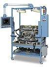
A pair of these pressure decay leak detectors were integrated into a high-speed automated assembly system for small medical check valves. Photo courtesy InterTech Development Co.
Checking Check Valves
The difficulty of disposable medical products is that they must be produced relatively inexpensively in high volumes, and yet they must also meet strict quality standards.
Recently, a systems integrator contacted InterTech Development Co. (Skokie, IL) to supply test equipment for a machine assembling small check valves for a medical device. The valves needed two leak tests and a function test, with the machine indexing eight check valves to the test equipment every 2 seconds.
InterTech provided two Model 1075 pressure-decay leak detectors to perform the three tests-a leak test at 220 inches of water column, a leak test at 5 inches of water column, and a forward direction test, or cracking pressure test, at 50 inches of water column to determine if the check valves closed appropriately.
One challenge was to create a station that could test eight parts simultaneously without taking up too much real estate on the assembly machine and without adversely affecting efficiency and productivity. A four-channel instrument, the Model 1075 could handle the volume requirements and still fit within the space constraints of the system. Each channel can operate independently or synchronously, depending on the testing criteria. Using two, four-channel instruments is significantly less expensive than eight one-channel instruments or four two-channel instruments.
Another tricky aspect of this application was the leak test at 5 inches of water column, which is an especially challenging pressure to maintain.
The leak detectors’ 24-bit, high-resolution convertors, which can detect minute pressure losses, were a critical factor in meeting the cycle time requirement of 0.8 second. Additionally, the integrator minimized the test circuit volume, so less time is needed to pressurize the valves.
A special feature of the system is the variety of connectivity options it provides, including Ethernet and RS-232 communications. Ethernet connectivity allows engineers to communicate with the leak detector through a web browser. That enables engineers to view diagnostics and troubleshooting options, as well as access on-line reference manuals. The leak detector also has a USB port, so engineers can attach additional instruments or download test results and programs.
For more information, visit InterTech at www.intertechdevelopment.com or call 847-679-3377.
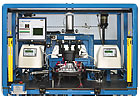
This test station automatically performs two leak tests, a flow test and a vacuum test on a plastic valve manifold for a water softener. Photo courtesy Forward Technology
Soft Water, Hard Problem
A water softener consists of two tanks. One contains resin beads that are saturated with sodium ions. The other contains brine. Hard water enters at the top of the resin tank and flows down through the beads. Softening occurs as minerals in the water attach themselves to the resin in exchange for sodium. The softened water then enters a long tube in the center of the tank, from which it flows to faucets throughout the house.When the beads become saturated with minerals, they must be regenerated with sodium. So, brine from the second tank is periodically pumped through the beads, which grab the sodium and give up their minerals. This mineralized water goes down the drain.
All this water flow is governed by a cam-actuated valve manifold made from plastic. Needless to say, the manifold can neither leak nor occlude the flow of water. That’s where Forward Technology (Cokato, MN) comes in. The company makes a variety of equipment for joining plastic parts, including ultrasonic, hot-plate and spin-welding machines. It also supplies equipment to check plastic assemblies for leaks and flow.
Recently, a water softener manufacturer asked Forward Technology to provide equipment to assemble and test a valve manifold. Designing a machine to assemble the manifold was relatively easy. Designing a machine to test the assembly for leaks and flow was tricky.
The manifold requires four checks: two pressure-decay leak tests, a flow test, and a vacuum test. During the test process, different valves in the manifold must open or close in a specific sequence. An operator could do this manually, but this would make the test process labor-intensive and error-prone. Forward’s engineers devised a way to open and close the valves automatically, using small linear actuators.
Coordinating the activity of testers and actuators is “the sort of thing we do really well, since we specialize in PLC-based test systems,” says Andrew Tapper, engineering manager for Forward Technology. “A standard, out-of-the-box leak tester typically can’t handle all that extra automation.”
Measuring 12 by 6 by 8 inches, the manifold is assembled with multiple hot-plate welds. After assembly, the manifold is manually loaded into the test station. When the machine is actuated, it inserts a series of plugs into the assembly, and the leak, flow and vacuum tests are performed automatically using ordinary air. “If any test fails, the machine pauses for the operator to take corrective action, either restarting a test or removing the faulty part,” says Tapper.
If the manifold passes all the tests, the machine automatically marks the part with a code. The entire process takes just under a minute.
For more information, call Forward Technology at 320-286-2578 or visit www.forwardtech.com.
Device Tests Fuel Rails
Leak testing every component that delivers fuel in an automobile is necessary to ensure engine performance, safeguard passengers and protect the environment. As regulations on releasing fuel vapors into the environment become stringent, component manufacturers have been forced to detect smaller and smaller leaks in their assemblies.Recently, a manufacturer of fuel rails contacted Alcatel Vacuum Products (Hingham, MA) to provide a leak-detection technique that was at least one order more sensitive than the pressure decay method. The system needed to have simple tooling, and it had to be more tolerant of background contamination than helium mass spectrometry. In addition, the new system had to be faster-or at least no slower-than the current testing method.
The manufacturer needed to test a fuel rail with a leak specification of 0.5 cc per minute at 72 psig. Because the part would be tested after brazing, it could be warm during testing, so the new system had to tolerate temperature changes in the part.
The solution was a leak detector that uses diluted hydrogen as the tracer gas-the H2000 Plus with an AP29 active probe. Diluted hydrogen (95 percent nitrogen, 5 percent hydrogen) is nonflammable, environmentally friendly and readily available. The leak detector is equipped with gas-field effect transistors (GAS-FET) that can detect leak rates as small as 5 x 10⁻⁷ cc per second.
To start the process, openings in the fuel rail are sealed, and the assembly is positioned in a simple chamber designed to work at atmospheric conditions. Closing the chamber initiates an automatic test cycle. Because the test is done under atmospheric conditions, the seals and materials for the part and chamber are not critical.
Once the rail is pressurized to 72 psig with the test gas, it sits for a short time to allow any leaking gas to accumulate in the chamber. During the accumulation time, the air inside the chamber is circulated with a fan. Next, the system draws an air sample from the chamber, analyzes it, and issues a pass-fail indication based on a preset alarm point. When the test is over, the system vents the gas from the component.
For more information, call Alcatel Vacuum Products Inc. at 781-331-4200 or visit www.adixen-usa.com.
The FIG connector grips and seals rough, cast parts and out-of-round ports with external beads. It mechanically grips the bead. Then, a pneumatically operated elastomer seal compresses into the inside diameter of the part to provide a leak-tight connection. Photo courtesy Fastest Inc.
Connector Aids Engine Testing
Whether it uses a tracer gas or air, every leak test system has one thing in common: The assembly being tested must be effectively sealed and fixtured. Without good fixturing, even the best leak testing system will not provide reliable results.Fastest Inc. (Roseville, MN) makes connectors for transferring liquids and gases, such as helium, propane and refrigerants, to and from assemblies. Leak testing is a major application for the company’s products.
Recently, a manufacturer of large diesel engines contacted Fastest for help with a leak testing challenge. Because of more stringent emissions laws, exhaust gases from a diesel engine must pass through a filter before reaching the air. The engine maker had to test the large, cylindrical manifold leading to the filter for leaks. The challenge was the size of the opening that had to be sealed for the test: It was approximately 6 inches in diameter.
Initially, the engine maker used a simple cam-over plug to seal the manifold. This device uses a lever-operated cam-and-pawl mechanism to create the seal. Though simple and inexpensive, cam-over plugs have some limitations, explains Mark Spindler, customer service manager at Fastest. Because the elastomer seal takes a compression set quickly, the plug loses effectiveness over time, especially with large-diameter holes. To compensate for this set, the connectors require manual adjustments to increase compression on the seal. As a result, getting consistent test results can be difficult. Finally, bumping the lever can cause the connector to accidentally pop off, putting operators at risk of injury.
The FIG connector from Fastest proved to be a better alternative. The connector grips and seals rough, cast parts and out-of-round ports with external beads, which are common on manifolds. The FIG mechanically grips the bead. Then, using shop air at 60 to 90 psi, a pneumatically operated elastomer seal compresses into the inside diameter of the part to provide a leak-tight connection. The internal seal is activated by a piston, which expands an elastomeric material-either neoprene or urethane-to form a leak-tight connection. Testing, filling or flushing the piece is accomplished by introducing air, liquid or gas through the connector port.
Because the connector is pneumatically actuated, rather than mechanically actuated, no operator adjustment is needed. In addition, the gripping feature on the connector is less vulnerable to accidental disengagement than a lever, minimizing risk to the operator. As a result, the engine maker’s leak testing process is both safer and more accurate.
Fastest developed the FIG connector specifically for the engine-testing application. Previously, the company had only offered a 4-inch connector. Increasing the size of the connector to 6 inches required more than just changing a few dimensions, explains Spindler. Fastest’s engineers knew that, as the size of the connector increased, the forces from operating pressure and test pressure would increase exponentially. If such forces were unbalanced, it could lead to seal extrusion or displacement. Unbalanced forces and seal containment had to be carefully analyzed to ensure that the connector would work as intended.
For more information, visit www.fastestinc.com or call Fastest at 800-444-2373.
This machine checks a transmission housing for leaks. Photo courtesy Advanced Test Concepts Inc.
Setting the Right Spec
Often, the most challenging aspect of leak testing an assembly isn’t designing the test process-it’s establishing a specification for leak tightness that makes sense. In many cases, specifications such as “no bubbles for 30 seconds,” “no leaks allowed,” or “30 standard cc per minute at 10 psig” are set arbitrarily and don’t correlate well with the actual performance requirements of the assembly.However, as a manufacturer of transmissions for trucks and off-road vehicles recently learned, setting a sound specification for leak tightness is critical for establishing a leak testing process that is both reliable and cost-effective.
Truck transmissions are large, complex assemblies that are challenging for any leak testing technology. Housed in complex metal castings, they must be checked for both internal and external leaks. The problem with castings is porosity-tiny bubbles in the metal caused by internal shrinkage, gas cavitation, oxide films and inclusions. These small voids are often invisible, but they nevertheless provide a way for fluids or gases to escape. Needing a reliable leak test strategy, the transmission maker turned to Advanced Test Concepts Inc. (ATC, Indianapolis) for help.
The first step was to set meaningful leak tightness specifications for the components and the final assembly. When setting such specifications, ATC recommends an approach called equivalent microgeometry (EMG). The EMG is the largest, single flow path for leaks that can be tolerated in an assembly. For the truck transmission, the EMG represents the widest pinhole that will not leak transmission fluid. Anything larger will leak transmission fluid at operating conditions.
The EMG approach is generic and independent of the method used to leak test the assembly, explains Hemi Sagi, director of ATC. Although the flow rate of air or a tracer gas can be correlated to flow path geometry for leaks, these correlations are often oversimplified, resulting in leak tightness specifications that are too strict or too lax.
Lab tests conducted by ATC and dynamometer tests conducted by the transmission manufacturer established the EMG for the high- and low-pressure oil cavities in the transmission.
In the end, the transmission manufacturer set a tighter leak specification for individual components of the transmission than for the final assembly. That’s because the goal for testing the components is to check for porosity in the castings and defects in the sealing surfaces, whereas the purpose of testing the final assembly it is to find assembly errors and missing or defective seals.
The leak specification for the components was tight, so the fixture and seals had to be carefully designed. Furthermore, the functional seal line of the components had to be part of the test, so defects in the sealing surfaces could be detected.
ATC’s Model E leak test instrument was used to test the components, while the Model IPE was used to test the fully assembled transmissions. Both instruments were equipped with ATC’s microflow sensor, the Intelligent Gas Leak Sensor (IGLS). Using air, the IGLS can detect small leaks that are typically require helium mass spectrometry to measure.
Given the large test volume (15 gallons or more) and short cycle time (approximately 60 seconds) for the assembled transmission, a stable sensor was needed to ensure consistent results from day to day. In addition, the test instruments had to be flexible, because the test volume varied depending on the transmission model.
Engineers performed numerous tests to optimize the parameters. An optimum test circuit was developed to ensure a stable and quick-charging process with the ability to detect leak rates in the range of 10 cc per minute at approximately 10 psig.
For more information, call ATC at 317-328-8492 or visit www.atcinc.net.
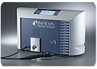
This sniffer-style leak detector is used to test an hydraulic assembly. To run a test, the assembly is pressurized with helium. Then, an operator scans joints with a sniffer probe. Inside the leak detector, precision sensors identify abnormal amounts of helium. Photo courtesy Inficon
Helium Helps Hydraulics
The goal of any test or inspection process is to catch defects early, when they are inexpensive to fix. This is particularly true for large assemblies with many parts, such as hydraulic actuators. Disassembling a finished actuator to fix a leaky joint wastes considerable time and money.Thus, a manufacturer of heavy-duty hydraulic components wanted to leak test a critical circuit joint before any more value could be added to the assembly. The joint consisted of two metal fittings and a gasket or O-ring. The diameter of the fittings ranged from 1 to 5 inches. The assembly could not leak more than one drop of hydraulic fluid over a three-year period, despite high temperature conditions and operating pressures of more than 2,000 psig.
The Protec P3000 helium leak detector from Inficon (East Syracuse, NY) handled the job. The P3000 is a sniffer-style leak detector. To run a test, the assembly is pressurized with helium. Then, an operator scans each joint with a sniffer probe, which inhales gas at a high rate. Inside the leak detector, finely tuned sensors identify abnormal amounts of helium. The amount of helium in the gas load corresponds with the leak rate.
As with any leak testing application, the key challenge was correlating a leak rate for helium with the manufacturer’s maximum leak specification for hydraulic fluid. To accurately simulate years of liquid leakage in a 60-second leak test, Inficon engineers constructed computer models of the assembly, ran tests on the line, and examined the behavior of the joint under various failure modes. Additional studies were done to set test time and pressure. This wasn’t easy, since the joint was designed to hold hydraulic fluid rather than pressurized helium.
To complicate matters, the assembly had a high-pressure side and a low-pressure side. To optimize testing, both sides had to be tested at the same time and at the same pressure. However, because the low-pressure side determined the maximum test pressure, the high-pressure side would end up being tested at a much lower pressure than its operating pressure. This meant that a leak on the high-pressure side would be harder to detect, since less gas would be escaping. The P3000 worked well in this application, because it was sensitive enough to detect the smaller leak.
During the test engineering phase, the operators found that the P3000 could find leaks from a long distance. Its fast response to leaks, even with a long probe, gave operators flexibility to conduct tests more ergonomically. The stability of the unit allowed operators to trust the signal, instead of fretting over false alarms. Fast “cleanup” of the helium enabled operators to quickly retest assemblies to confirm the location of any leaks.
For more information, call Inficon at 315-434-1100 or visit www.inficon.com.
Looking for a reprint of this article?
From high-res PDFs to custom plaques, order your copy today!


