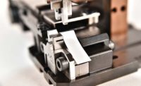
A wire terminal for crimping consists of a mating section, a transition section and a crimping zone. The mating section is the part of the terminal that mates with the other half of the connection. The transition section contains stops or locking tangs that keep the terminal in place in the final product. Also known as the barrel, the crimp section is the part of the terminal that is deformed during crimping. Some terminals have two barrels: one for the wire and a second for the insulation. This extra barrel gives the joint added strength.
As a terminal is crimped, the terminal's barrel presses around the conductor with enough force to deform both the wire and the barrel, creating a cold weld between the two parts and establishing gastight connection. If done correctly, the terminal becomes an extension of the wire.
Wire preparation is critical for making a good crimp. If using mechanical strippers, assemblers should avoid nicking or removing wire strands, because it can decrease the tensile strength of the crimped joint. Tensile strength will also decrease if the insulation is not completely removed.
Heat stripping eliminates the danger of nicking strands. However, depending on the material, too much heat can char the insulation or produce gases that corrode conductor platings. Excessive heat can also cause local annealing of the conductors. Conversely, too little heat can deposit an insulation film on the conductors, which can act as a lubricant.
Strip length is also important. The wire should extend all the way into the barrel of the terminal. If the strip length is too short, there won't be enough conductor for the barrel to grip. If it's too long, there won't be enough material for an insulation barrel to grip. Either way, the strength and the conductivity of the joint will be compromised.
Termination Equipment
A variety of wire termination equipment is available, ranging from hand tools to semiautomatic and fully automatic machines. Which type to use depends on:- The type of terminal, including its size, shape, material and function.
- The type and size of the wires.
- Production volume and variety requirements. Because of the risk of hand and wrist injuries to operators, manual crimping tools should be reserved for repair, prototyping and low-volume production runs. These tools come in pliers or pistol-grip configurations, and some models offer adjustable and interchangeable crimping dies. To protect operators, tools with cushioned, ergonomic grips are recommended.
For semiautomatic assembly at higher volumes, a benchtop press is necessary. Like bench-mounted power tools, crimping presses can be electric or pneumatic. They can produce more than 2,000 terminations per hour and are used most often to apply open-barrel terminals manufactured in "daisy chains" and supplied on reels. Terminals can be made side-by-side or end-to-end. In some crimping presses, the chain enters the press from the side. In others, it comes in from the rear.
For small wires (conductor cross sections of less than 10 square millimeters), a typical press will have a stroke of 30 to 40 millimeters and supply a crimping force of 10 to 50 kilonewtons. For larger wires, a typical press might have a stroke of 50 millimeters and supply a crimping force of as much as 100 kilonewtons.
Also known as applicators, crimping dies for presses are made specifically for a particular terminal. Dies can be made to apply two terminals at the same time or to perform two processes at the same time, such as crimping and bending. Crimping dies wear with use and should be replaced occasionally. In some cases, dies can be purchased from manufacturers other than the OEM.
To install a terminal, the operator inserts a stripped wire into the press. A sensor activates the crimping process automatically, or the operator can trigger the machine with a foot pedal. A clamping device secures the wire and brings it to the die, where the terminal is cut from the reel, placed over the wire end, and crimped. (Waste material from the terminal chain is collected in a receptacle.) The whole process takes from 0.2 to 1.5 seconds.
Some crimping presses can strip a wire before applying the terminal, and others can apply a weather seal to the joint. Among helpful options for presses are batch counters, switches to prevent operation when safety equipment is not in place, and small lamps to help operators feed wires into the die. Another press option is a sliding table. This tool enables the operator to insert the components to be processed outside of the crimping area. After the parts are positioned, the operator slides the table into the crimping area and activates the machine. This tool is used to attach delicate parts, such as sensors, onto wires.
Some crimping presses can be equipped to work within a fully automated wire processing system. Besides one or more presses, such a system might include:
- Automatic wire cutting, stripping and marking machines.
- Weather seal applicators supplied by feeder bowls.
- A machine for making twisted pairs.
- Quality control monitors for strip length, crimp strength and seal presence.
- A device for connecting two wires.
- Stations for fluxing and tinning conductors.
- A robot to shuttle wires from one station to another. hese systems can be programmed to apply one or more types of terminals to one or both ends of a wire. Depending on the number of actions it performs, a fully automatic wire processing system can produce a complete assembly in 1.5 to 3 seconds.
Was It Done Right?
When crimped correctly, the electrical resistance of a wire-and-terminal assembly should be equal to or less than the resistance of an equal section of wire alone. Design engineers often specify a maximum loss of resistance for the connection, usually a millivolt drop at a designated current. Assemblers should measure the electrical resistance of finished wires prior to full production and spot-check it thereafter. If electrical resistance is critical to the finished product, it's best to check it before the assembly is integrated into a wire harness.Another quality variable to watch is the mechanical strength of the crimped joint. This is measured as the tensile, or pull-out, force needed to separate a wire from a terminal. The mechanical strength of a crimped joint depends on how it is deformed. The shape of the crimp and the force used to produce it can make a big difference. Too little force will produce a loose connection and high electrical resistance. Too much force can overstress the conductors and cause the wire to break-off later.
Off-line, assemblers can check crimp strength with a handheld tester or a benchtop test stand. Either way, the process is the same. The terminated end of the wire is fixed, and the device slowly pulls on the wire until it separates from the terminal. This is the most direct measure of joint strength, but it is, of course, destructive. As a result, it should be reserved for preproduction testing and spot checks.
For nondestructive, on-line testing, assemblers must check crimp strength indirectly by measuring crimp force and crimp size. This is accomplished with an electronic crimp quality monitor. Using sensors mounted on the applicator or the press, the monitor checks crimp height as well as the shape of the force curve for each crimping cycle. Variations in either measurement may indicate:
- Tooling wear.
- The wrong wire was used.
- The wire or terminal is missing.
- Strands of wire escaped from the barrel.
- The wire was inserted into the barrel too far or too short.
Resources
ASSEMBLY would like to thank the following companies for their contributions: Application Tooling Solutions, Astro Tool Inc., Crimping & Stamping Technologies Inc., Daniels Manufacturing Corp., ETCO, Glenair Inc., Hanke Crimp-Technik, Hellerman Tyton, JST Corp., Kirsten North America Inc., KMI, Komax Corp., Makfil Systems, Megomat USA Inc., Molex Inc., Pawo Systems AG, Ram Electronics, Schaefer Technologies Inc., ShinMaywa America Ltd., Standard Pneumatic and Electric Tool Co., Toyojamco Ltd. and Tyco Electronics Corp.The Rap on Wire Wrapping
In 1952, Bell Laboratories proved that a wire tightly wrapped around a terminal with two sharp edges could form a consistent, gastight electrical connection without soldering. Since then, the electronic, telecommunication and aviation industries have adopted wire wrapping as a reliable and inexpensive means for solderless connections. Wire wrapping is commonly used to connect signal and power terminals in advanced electronic systems.Wrapped connections have excellent mechanical and electrical stability due to their gastight contact area. They remain stable despite exposure to severe temperature changes, humidity, corrosive atmospheres and vibration. High contact pressure and the high shearing force of the wire on the corners of the terminal remove surface contamination from the wire and the terminal. This produces an intimate, clean, oxidation-free, metal-to-metal contact with a large area. Initial pressure at the center of the contact area may be as high as 100,000 psi. After wrapping is complete, cold flow causes pressure to drop to approximately 30,000 psi, at which point the metal stabilizes and the pressure remains constant.
Wire wrapping is accomplished with manual, electric, battery-powered or pneumatic hand tools. The operator inserts and anchors a stripped wire into the wrapping bit of the tool. The terminal is then inserted into the center hole of the wrapping bit, and the tool is activated. The tool rotates the bit, wrapping the wire around the terminal. Some bits can cut, strip and wrap the wire in one process.
Any good-grade, solid conductor with normal ductility can be used as the wrapping wire, but the most common choice is tin-plated copper wire. The tinning makes no difference in the quality of the connection, but it is helpful if the connection is soldered later.
Although wire-wrapped connections are quick and permanent with good mechanical and electrical qualities, they may be easily removed if necessary without damaging the terminal. To remove the connection, an unwrapping tool is placed over the terminal, engaging the first turn of the connection. Rotating the tool removes the connection in seconds.
For more information on wire wrapping, call Standard Pneumatic and Electric Tool Co. at 800-648-5055, visit www.stdpneumatic.com.
Terminating Terminology
Applicator: A crimping die.Butting die: A crimping die in which the nest and indenter touch at the end of the crimping cycle.
Circumferential crimp: A type of crimp in which the crimping dies surround the barrel, resulting in symmetrical indentations in the barrel.
Conductor barrel: The section of a terminal that accommodates the stripped conductor. It is the part that gets crimped.
Connector: A device, either a plug or a receptacle, used to terminate or connect the conductors of individual wires or cables. A connector provides a means to continue the conductors to a mating connector or printed circuit board.
Crimp: The compression of a terminal barrel around a conductor to make an electrical connection.
Crimp depth: The distance the indenter penetrates into the barrel.
Indenter: The part of a crimping die that indents or compresses the contact barrel.
Insulation barrel: The section of a terminal that accommodates the conductor insulation. It can be crimped.
Insulation displacement connector: A process in which a contact pierces through the wire insulation to contact the conductor.
Locator: A device for positioning terminals in crimping dies.
Nest: The portion of a crimping die that supports the barrel during crimping.
Pull-out force: The tensile force needed to separate a wire from a terminal.
Terminal: A device attached to the end of a wire or cable for conveniently making electrical connections.


