New Technology for Robotic Welding
A new generation of robots is helping assem-blers weld parts better, faster and more cost-effectively.
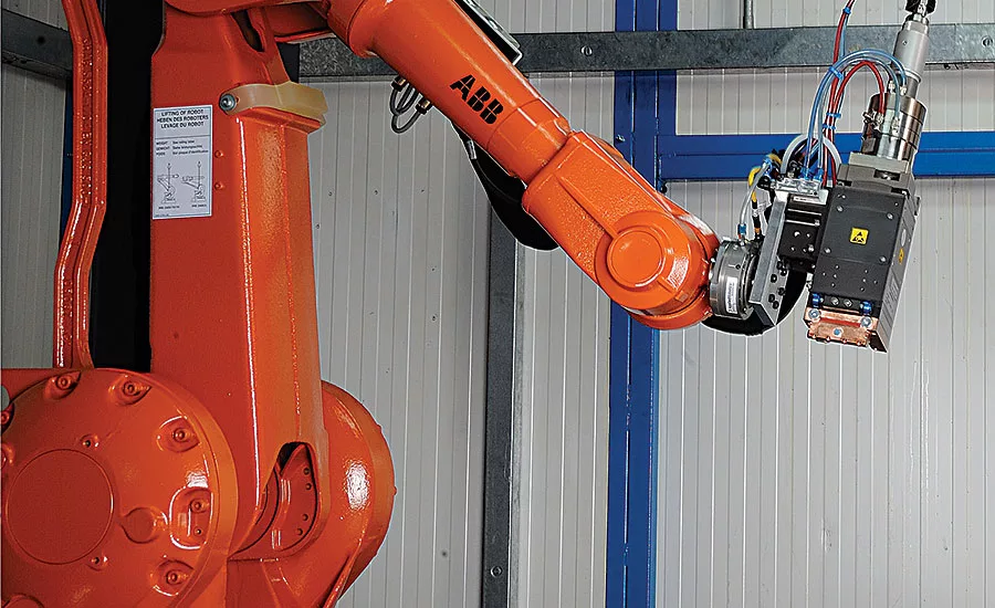
Driven by demand from the automotive industry, laser welding is one of the fastest growing applications for six-axis robots. Photo courtesy ABB Robotics
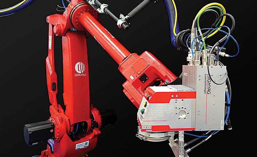
The dress package for laser welding requires some care to set up. Bend radius restrictions must be adhered to, and the cables can’t take shock. Photo courtesy Comau LLC
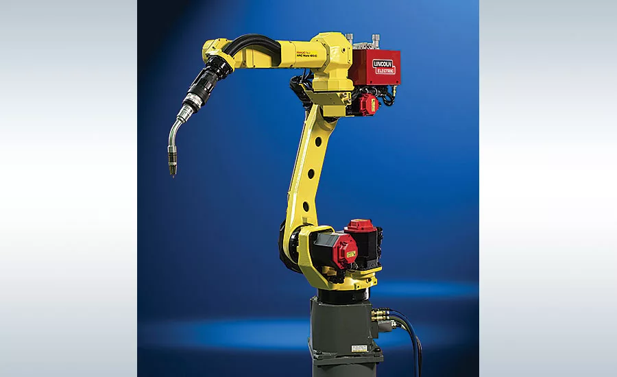
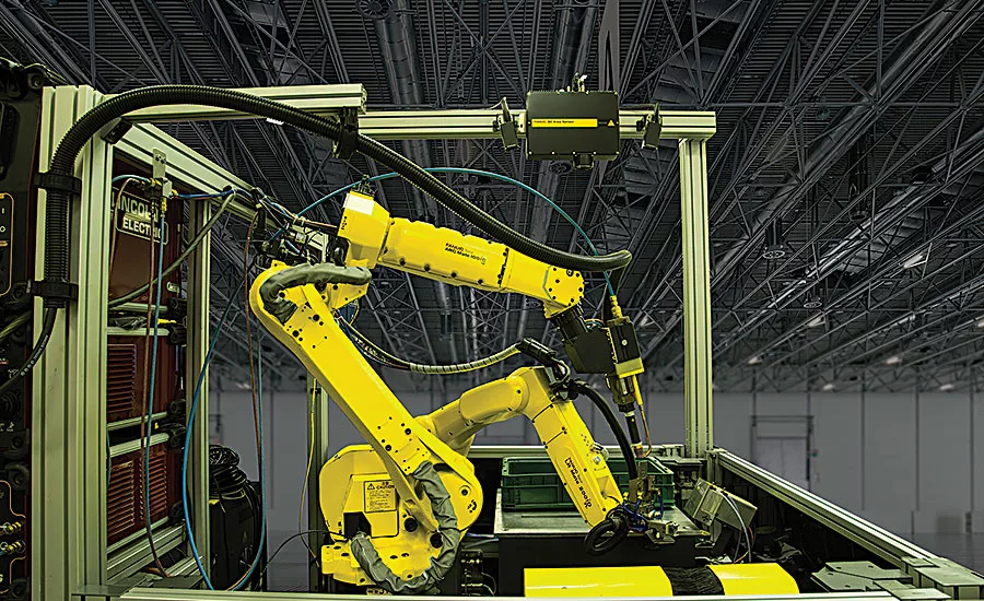
Whether the robot will be used for GTAW or GMAW, experts recommend a machine specifically designed for the task. Photo courtesy FANUC America Corp.
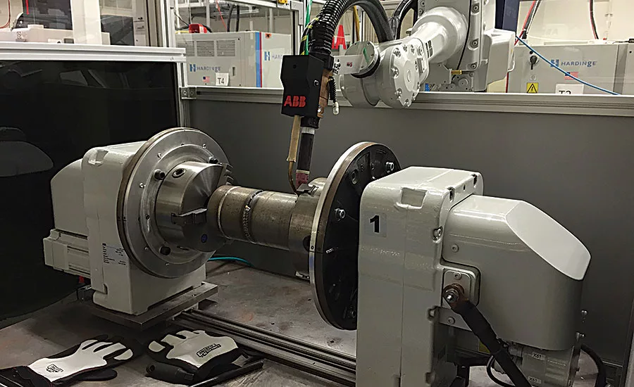
ABB has recently added the TIP TIG process to its platform of robotic welding technologies. Instead of supplying the filler wire into the weld pool at a continuous rate, the feeder agitates the wire back and forth. Electrical current, supplied by a secondary power source, is also applied to the filler wire. Photo courtesy ABB Robotics
With fixtureless welding, the base part is located in a simple fixture. Then, a vision-guided, material handling robot picks up the part to be welded, sets it in place on the base part, and holds it there while an arc welding robot does its task. Photo courtesy FANUC America Corp.
Welding of one sort or another has been the No. 1 application for industrial robots almost since the technology was invented.
According to the International Federation of Robotics, 50 percent of all the world’s robots are used for welding. Specifically, 33 percent are employed for spot welding, 16 percent are doing arc welding, and 1 percent are performing some other type of welding operation.
With six-axis robots, assemblers can weld parts better, faster, more consistently and more safely. And, the capabilities of welding robots have improved dramatically in recent years, even as they have become easier to use and less expensive to deploy. A technology that was once solely the province of automotive OEMs and other large manufacturers is now well within the reach of small- and medium-sized enterprises.
Small wonder, then, that the worldwide market for welding robots is expected to grow 6.09 percent annually through 2019, according to market research firm Technavio.
Robotic Laser Welding
Driven by demand from the automotive industry, laser welding is one of the fastest growing applications for six-axis robots. Automakers are under pressure to reduce vehicle weight, and laser welding addresses that problem on several fronts, says Mark Anderson, materials and technology director at Comau LLC.
For example, to save weight, automakers are increasingly using hydroformed tubes for various chassis components. Joining sheet metal to such tubes poses a problem for resistance spot welding, which requires access to both sides of the assembly. Laser welding doesn’t share that limitation. It only requires access to one side of the assembly.
In addition, because the focal point of the laser beam is so small, part flanges for lap joints can be narrower than those designed for resistance spot welding, says Anderson. Less metal means less weight and lower costs.
Looking for quick answers on assembly and manufacturing topics? Try Ask ASM, our new smart AI search tool. Ask ASM
“The end caps on a spot welding gun might be 0.25 inch in diameter,” he explains. “That means the flange has to be at least 10 or 12 millimeters wide. With laser welding, you can have a spot size of 1 millimeter in diameter. Now, your flange can be just 3 or 4 millimeters wide. That’s a 50 percent savings in material.”
The need to reduce vehicle weight also has automakers assembling car bodies with a variety of materials in a variety of thicknesses. At one time, all the parts of a door panel might have been stamped from the same roll of sheet steel. Today, that same door panel might consist of five different materials of varying thicknesses.
Laser welding can help with that challenge, too. “A laser beam can produce much more heat than GMAW [gas metal arc welding],” says Mark X. Oxlade, market development manager for welding and cutting at ABB Robotics. “Dissimilar materials can be joined more easily at these higher temperatures.”
Due to the size of the end-of-arm-tooling (EOAT), resistance welding requires a fairly hefty robot with a high payload capacity, around 100 to 250 pounds. On the other hand, the tooling for GMAW is smaller and lighter, so a robot with a payload capacity of 20 to 40 pounds might be sufficient.
Laser welding is somewhere in the middle, says Anderson. These days, the laser light source itself—a fiber, diode or disk laser—is not part of the EAOT. Rather, the laser is located well away from the robot, and the beam is delivered to the EAOT via fiber optic cable. Thus, the robot only needs to carry various optics (the laser head), cables and auxiliary tooling, such as a pressure wheel to help clamp parts together during welding. As a result, assemblers may only need a robot with a payload capacity of 60 to 90 pounds.
On the other hand, robots with a lower payload capacity generally have a shorter reach, as well. So, if a larger work envelope is desired, assemblers may want to upgrade to a higher capacity robot.
The dress package for a laser welding robot is similar to that for other types of welding robots, except that fiber optic cables substitute for electrical cables.
“The dress package for laser welding requires some care to set up, probably more so than with resistance spot welding,” cautions Anderson. “Bend radius restrictions must be adhered to, and the cables can’t take shock.”
Laser suppliers like Trumpf Inc. and IPG Photonics Corp. are working closely with robotics OEMs so the two technologies work harmoniously. For example, ABB has developed an interface that enables Trumpf’s Programmable Focusing Optics (PFO) laser head to be controlled via ABB’s robot controller rather than an external PC.
“That produces huge improvements in cycle time,” says Oxlade. “One-third to two-thirds of the typical cycle time can be eroded purely by that capability. Historically, you used to have to move to one point, weld it, move to another, etc. Now, the software simply enables you to do it as one sweeping move, and that’s a big cycle time savings.”
The PFO positions the laser beam with two rotating mirrors to maximize processing and positioning speeds and reduce overall cycle time. The laser beam can be placed at any predefined position within the process space, or it can be guided over any contour. Spot welding, stitch welding, continuous seam welding, and cutting are possible without moving the workpiece or the focusing optic.
The PFO is available for both pulsed and continuous-wave solid-state lasers. Different focal lengths ranging from 90 to 1,200 millimeters enable different processing field sizes.
Processing can be done “on the fly” to minimize positioning times due to overlap of robot and scanner movement. Depending on the focal length, working areas from 56 by 56 millimeters to 406 by 630 millimeters can be achieved.
With the PFO, the wobble movement of the laser spot is individually adjustable for optimal weld seam quality with both heat conduction welding and deep-penetration welding.
“A laser beam is very thin,” explains Oxlade. “So if it doesn’t hit the mark exactly, quality can degrade. With the PFO, you can diffuse the beam. You can dither and wobble the beam, a bit like weaving in arc welding.”
Thus, a high-quality weld can still be produced even if the positioning of the parts is off a little bit.
Robotic Arc Welding
Though robotic laser welding has commanded a lot of attention lately, robotic arc welding technology has improved significantly in recent years, too.
For example, ABB has recently added the TIP TIG process to its platform of robotic welding technologies. Developed by TIP TIG International AG, the process is a variation of gas tungsten arc welding (GTAW). Instead of supplying the filler wire into the weld pool at a continuous rate, the feeder agitates the wire back and forth. Electrical current, supplied by a secondary power source, is also applied to the filler wire.
GTAW has been notoriously difficult to do with six-axis robots, because part fit-up prior to welding had to be precise and repeatable, explains Oxlade.
“Vibrating the filler wire makes the process more forgiving to the fit of the parts and makes it easier to wet-up of the sides of the joint,” he says. “There are other benefits, too, like lower heat input and higher travel speeds. Ordinarily, GTAW is extremely slow, but with robotic TIP TIG, you can approach GMAW speeds.”
Whether the robot will be used for GTAW or GMAW, experts recommend a machine specifically designed for the task.
A good example is the ARC Mate 100iC/8L from FANUC America Corp. Introduced last fall, the robot has a 2,028-millimeter reach and 8-kilogram payload.
Like all FANUC robots, the ARC Mate 100iC/8L operates with the company’s latest R-30iB controller with integrated intelligent functions, such as vision and integrated secondary control, Roboguide Simulation, and DCS Speed and Position Check Software.
In addition to the Model 8L, the ARC Mate 100iC series includes the Model 12 with a 1,420-millimeter reach and a 12-kilogram payload, and the Model 7L with a 1,632-millimeter reach and a 7-kilogram payload. The robots can be mounted to the floor, overhead or at an angle, and joint 3 can be flipped.
“One of our main goals in designing the 100iC series was to create a robot with a compact footprint, but a maximum reach and stroke to reach around any part and orient the torch to different areas of the part,” says Mark Scherler, general manager for materials joining at FANUC America Corp.
All the 100iC robots have a hollow wrist, which simplifies routing of cables and tubes, eliminating cable management issues, says Scherler. Compared to traditional dress packages, which are mounted externally on the robot’s arm, the internal routing of the ARC Mate 100iC allows the dress package to follow the motion range of the robot, simplifying programming and eliminating the worries of bending, snagging or breaking cables.
ARC Mate 100iC robots and the R-30iB Controller can be integrated in a welding system that includes the weld torch cable, wire feeder, and welding power supply. FANUC has worked closely with welding equipment supplier Lincoln Electric Co. to develop an Ethernet-based interface—ArcLink XT—between the robot controller and the welding power supply.
“As a result, all the setup work for a robotic arc welding application can be done through the robot’s teach pendant,” explains Scherler. “No additional programming needs to be done with the power supply.”
Another new technology for robotic arc welding is “fixtureless welding.” Ordinarily, robotic arc welding requires parts to be positioned rigidly and precisely in a costly fixture that is typically designed just for that application.
With fixtureless welding, the base part is located securely in a simpler fixture. Then, a vision-guided, six-axis robot designed for material handling picks up the part to be welded, sets it in place on the base part, and holds it there while the 100iC arc welding robot performs its task.
“With fixtureless welding, your capital costs go down. You’re not building special fixtures for every job. It gives you more flexibility,” says Scherler.
Looking for a reprint of this article?
From high-res PDFs to custom plaques, order your copy today!


