Robotics: Guidance Goes 3D
With 3D vision guidance, robots can pick parts from leaning stacks, insert complex parts into assemblies, and even retrieve randomly distributed parts from a bin.

A German automotive manufacturer was successfully using a six-axis robot to handle transmission cases. An overhead conveyor carried the cases to the robot. The cases rode on fixtures with precision locating pins to ensure accurate positioning. The robot would pick up a case, present it to a machining and cleaning operation, and return it to the tray.
The system had been working flawlessly for three years, then suddenly, it began to experience intermittent downtime. The robot was having difficulty locating and grasping the cases. The problem was with the fixtures. Over time, the pins had worn down and the fixtures had deformed. The company faced an expensive dilemma: replace 100 fixtures or live with the downtime.
Steven W. West, development manager for vision-guided robotics at ABB Inc., had a better idea. He retrofitted the robot with a 3D vision guidance system. With 3D vision, the robot could determine the precise location of each transmission case, despite minor variations in positioning. “It proved much less costly than refurbishing the entire conveyor,” he says.
Assemblers have long used 2D vision guidance to maximize the flexibility and cost-cutting power of robots. Now, suppliers of robots and vision systems are taking vision guidance to the next level: 3D imaging. “You can solve a lot of problems with 2D vision, but you can solve even more with 3D vision,” says West.
Without vision, a robot simply moves where it’s told. For the robot to pick a part, it must be positioned in the same X, Y location, and in the same orientation, accurately and repeatably. Precision fixtures or trays are needed to accomplish this.
Adding vision gives assemblers greater flexibility in how they present parts to the robot, says Kevin Taylor, vice president of the automotive business unit of ISRA Vision Systems Inc. With 2D vision guidance, the robot can locate parts positioned with three degrees of freedom: X, Y and rotation around Z. This type of system is fine for locating singulated parts loosely positioned on a flat surface, such as a conveyor. It works best with parts that have only one resting position.
Adding extra dimensional information gives assemblers that much more flexibility in presenting parts. With 2.5D vision guidance, the robot can find parts positioned with four degrees of freedom: X, Y, Z and rotation around Z. This type of system is useful for palletizing and depalletizing. In such applications, the height of a box may not be apparent to an overhead camera that only sees in two dimensions.
With full 3D vision guidance, the robot can locate parts positioned with six degrees of freedom: X, Y, Z, roll, pitch and yaw. With 3D guidance, a robot can retrieve parts from a shipping container with multiple layers of parts sandwiched between cardboard liners. The location of parts near the center of the liner might be fairly consistent. However, due to sagging, parts near the edges will likely be tilted down and away from the center. Or, consider a container without any dunnage, the parts left to lie where they may. Picking randomly oriented parts from a bin is impossible for a robot without 3D vision guidance.
With 3D vision guidance, robots can place parts into racks; pick parts from leaning stacks; and accurately locate large, hard-to-fixture parts.
Three-dimensional vision guidance is useful for more than just telling a robot where and how to pick up a part, adds Taylor. It can also show a robot where to install a part, where to dispense an adhesive or where to make a weld. For example, automakers use the technology to help robots install window glass or body panels. It’s also used to guide robots for dispensing seam sealant.
The technology does have limits. For example, if the part is tilted more than 30 degrees in X or Y, a guidance system may be unable to identify it. Guidance systems can also have difficulty with objects that don’t have consistent shapes. “A big challenge is how to find objects that are not identical, such as bags of potato chips or sacks of grain,” says West.
Which to use depends on the application. For example, camera-based systems work well with parts that have many geometric features, while laser scanning systems may be better for smooth parts with few geometric features, says West.
In the TruView system from ABB, a single camera and variable LED lighting are mounted to the robot. The system can provide 2D, 2.5D and 3D data with no change in hardware. To obtain 3D data, the robot moves to one position and takes a picture of the part. It then moves to another position and takes a second image. Sophisticated algorithms calculate the 3D position by comparing the shape of the part in the two images. “Think of a circle,” explains West. “The farther away it is, the smaller it gets. The closer it is, the larger it gets. If you position it on an angle, it becomes an ellipse.”
The 3DL system from FANUC Robotics America Inc. uses a standard camera and a laser to obtain 3D positional information. The camera and laser can be mounted to the robot or in a fixed location. The camera locates the part in X, Y and rotation around Z, like any 2D vision system. The laser determines yaw, pitch and height. To do this, the laser projects a pair of intersecting perpendicular lines on the object.
“The point where the lines intersect gives us Z,” explains Steve Prehn, senior product manager for vision at FANUC. “If the surface we’re looking at is angled with respect to the camera, the intersecting lines will be elongated in one direction-the direction that the surface points toward. [The mathematical relationship between the lines and angles] gives us pitch and yaw.”
The system works with both flat parts and round parts. The system is particularly valuable for locating parts that don’t have a lot of surface features, says Prehn. Normally, a 2D image of a complex part, like an engine block, will have a wide range of grey tones that correspond with changes in depth. “But, with a large, contoured, injection-molded plastic part, you may not get a lot of grey-level data,” he says. “One contoured edge can look like another quite easily. Our system creates a depth map of the part.”
FANUC’s 3D vision guidance system was instrumental to an application for one automaker. The company uses a six-axis robot to mount the front wheels to their hubs. The vision system locates the studs and determines the angular position of the hub. The robot then tilts and rotates the wheel to match the position of the hub and studs. (FANUC recently completed a similar application involving the tub for a washing machine.)
Because it uses a laser to obtain 3D data, the system has difficulty discerning the position of the laser on transparent parts and highly reflective parts.
Laser triangulation is the technology behind the Ranger 3D guidance system from SICK Inc. In this system, a laser projects a line onto the object at a defined angle, and a special camera records the angle of the light reflected back. The position of all the points along that line can then be calculated through triangulation. By passing the object through the line-or moving the line across it-the system can create a 3D profile.
“The system measures that profile at a rate of 35,000 times per second,” says Jim Anderson, machine vision product manager with SICK Inc. “Each column of the camera’s sensor has its own processor to find the position of the laser line and report it as fast as possible. Some of the calculations are done directly on the chip, so our system is very fast.”
Pinpoint accuracy, particularly in the Z axis, is a strength of the laser triangulation method. Indeed, the technology can be used to gauge parts at the same time it’s determining their location and orientation. “The system could scan a brake pad, for example, and compare it to a 3D CAD file of the part,” says Anderson.
The laser can be several feet away from the object. As with FANUC’s system, laser triangulation doesn’t work well with shiny or transparent materials.
A German automotive manufacturer was successfully using a six-axis robot to handle transmission cases. An overhead conveyor carried the cases to the robot. The cases rode on fixtures with precision locating pins to ensure accurate positioning. The robot would pick up a case, present it to a machining and cleaning operation, and return it to the tray.
The system had been working flawlessly for three years, then suddenly, it began to experience intermittent downtime. The robot was having difficulty locating and grasping the cases. The problem was with the fixtures. Over time, the pins had worn down and the fixtures had deformed. The company faced an expensive dilemma: replace 100 fixtures or live with the downtime.
Steven W. West, development manager for vision-guided robotics at ABB Inc., had a better idea. He retrofitted the robot with a 3D vision guidance system. With 3D vision, the robot could determine the precise location of each transmission case, despite minor variations in positioning. “It proved much less costly than refurbishing the entire conveyor,” he says.
Assemblers have long used 2D vision guidance to maximize the flexibility and cost-cutting power of robots. Now, suppliers of robots and vision systems are taking vision guidance to the next level: 3D imaging. “You can solve a lot of problems with 2D vision, but you can solve even more with 3D vision,” says West.
Without vision, a robot simply moves where it’s told. For the robot to pick a part, it must be positioned in the same X, Y location, and in the same orientation, accurately and repeatably. Precision fixtures or trays are needed to accomplish this.
Adding vision gives assemblers greater flexibility in how they present parts to the robot, says Kevin Taylor, vice president of the automotive business unit of ISRA Vision Systems Inc. With 2D vision guidance, the robot can locate parts positioned with three degrees of freedom: X, Y and rotation around Z. This type of system is fine for locating singulated parts loosely positioned on a flat surface, such as a conveyor. It works best with parts that have only one resting position.
Adding extra dimensional information gives assemblers that much more flexibility in presenting parts. With 2.5D vision guidance, the robot can find parts positioned with four degrees of freedom: X, Y, Z and rotation around Z. This type of system is useful for palletizing and depalletizing. In such applications, the height of a box may not be apparent to an overhead camera that only sees in two dimensions.
With full 3D vision guidance, the robot can locate parts positioned with six degrees of freedom: X, Y, Z, roll, pitch and yaw. With 3D guidance, a robot can retrieve parts from a shipping container with multiple layers of parts sandwiched between cardboard liners. The location of parts near the center of the liner might be fairly consistent. However, due to sagging, parts near the edges will likely be tilted down and away from the center. Or, consider a container without any dunnage, the parts left to lie where they may. Picking randomly oriented parts from a bin is impossible for a robot without 3D vision guidance.
With 3D vision guidance, robots can place parts into racks; pick parts from leaning stacks; and accurately locate large, hard-to-fixture parts.
Three-dimensional vision guidance is useful for more than just telling a robot where and how to pick up a part, adds Taylor. It can also show a robot where to install a part, where to dispense an adhesive or where to make a weld. For example, automakers use the technology to help robots install window glass or body panels. It’s also used to guide robots for dispensing seam sealant.
The technology does have limits. For example, if the part is tilted more than 30 degrees in X or Y, a guidance system may be unable to identify it. Guidance systems can also have difficulty with objects that don’t have consistent shapes. “A big challenge is how to find objects that are not identical, such as bags of potato chips or sacks of grain,” says West.
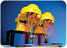
Any type of robot, including these compact delta robots, can benefit from 3D vision guidance. Photo courtesy FANUC Robotics America Inc.
Competing Technologies
Myriad technologies are available for 3D guidance. Some use one camera; some use two, three or even four. Some use a laser to project a geometric pattern onto the part. Others use a laser to scan the part, creating a point cloud akin to a 3D CAD model. Still others use time-of-flight cameras, which measure distances using short pulses of modulated light.Which to use depends on the application. For example, camera-based systems work well with parts that have many geometric features, while laser scanning systems may be better for smooth parts with few geometric features, says West.
In the TruView system from ABB, a single camera and variable LED lighting are mounted to the robot. The system can provide 2D, 2.5D and 3D data with no change in hardware. To obtain 3D data, the robot moves to one position and takes a picture of the part. It then moves to another position and takes a second image. Sophisticated algorithms calculate the 3D position by comparing the shape of the part in the two images. “Think of a circle,” explains West. “The farther away it is, the smaller it gets. The closer it is, the larger it gets. If you position it on an angle, it becomes an ellipse.”
The 3DL system from FANUC Robotics America Inc. uses a standard camera and a laser to obtain 3D positional information. The camera and laser can be mounted to the robot or in a fixed location. The camera locates the part in X, Y and rotation around Z, like any 2D vision system. The laser determines yaw, pitch and height. To do this, the laser projects a pair of intersecting perpendicular lines on the object.
“The point where the lines intersect gives us Z,” explains Steve Prehn, senior product manager for vision at FANUC. “If the surface we’re looking at is angled with respect to the camera, the intersecting lines will be elongated in one direction-the direction that the surface points toward. [The mathematical relationship between the lines and angles] gives us pitch and yaw.”
The system works with both flat parts and round parts. The system is particularly valuable for locating parts that don’t have a lot of surface features, says Prehn. Normally, a 2D image of a complex part, like an engine block, will have a wide range of grey tones that correspond with changes in depth. “But, with a large, contoured, injection-molded plastic part, you may not get a lot of grey-level data,” he says. “One contoured edge can look like another quite easily. Our system creates a depth map of the part.”
FANUC’s 3D vision guidance system was instrumental to an application for one automaker. The company uses a six-axis robot to mount the front wheels to their hubs. The vision system locates the studs and determines the angular position of the hub. The robot then tilts and rotates the wheel to match the position of the hub and studs. (FANUC recently completed a similar application involving the tub for a washing machine.)
Because it uses a laser to obtain 3D data, the system has difficulty discerning the position of the laser on transparent parts and highly reflective parts.
Laser triangulation is the technology behind the Ranger 3D guidance system from SICK Inc. In this system, a laser projects a line onto the object at a defined angle, and a special camera records the angle of the light reflected back. The position of all the points along that line can then be calculated through triangulation. By passing the object through the line-or moving the line across it-the system can create a 3D profile.
“The system measures that profile at a rate of 35,000 times per second,” says Jim Anderson, machine vision product manager with SICK Inc. “Each column of the camera’s sensor has its own processor to find the position of the laser line and report it as fast as possible. Some of the calculations are done directly on the chip, so our system is very fast.”
Pinpoint accuracy, particularly in the Z axis, is a strength of the laser triangulation method. Indeed, the technology can be used to gauge parts at the same time it’s determining their location and orientation. “The system could scan a brake pad, for example, and compare it to a 3D CAD file of the part,” says Anderson.
The laser can be several feet away from the object. As with FANUC’s system, laser triangulation doesn’t work well with shiny or transparent materials.
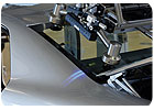
A laser-based 3D guidance system shows this robot exactly where to install the rear window on a vehicle. Photo courtesy ISRA Vision Systems Inc.
The Future
The advent of 3D vision could open the door to a number of intriguing robotics applications, including human-robot collaboration and mixed-load palletizing. When used in combination with tactile feedback, 3D vision could enable robots to perform complex assembly tasks, such as gear assembly or inserting circuit cards into motherboards.Looking for a reprint of this article?
From high-res PDFs to custom plaques, order your copy today!


