Improving Cycle Time in Robotic Workcells

An assembler was using a robot to load and unload a machine. The robot would load a part, wait for the process to finish, unload the part, and pick up a fresh one-a perfect application. And yet, there was still room to improve. This article provides tips and tricks for reducing cycle time in robotic workcells.
 Many
years ago, Sen. Everett Dirksen is reported to have said, “A billion here, a
billion there, and pretty soon you’re talking real money.” Assemblers looking
to decrease the cycle times of robotic workcells might paraphrase Dirksen as
follows: “A second here, a second there, and pretty soon we’re seeing real
improvement in efficiency, throughput and profits.”
Many
years ago, Sen. Everett Dirksen is reported to have said, “A billion here, a
billion there, and pretty soon you’re talking real money.” Assemblers looking
to decrease the cycle times of robotic workcells might paraphrase Dirksen as
follows: “A second here, a second there, and pretty soon we’re seeing real
improvement in efficiency, throughput and profits.”
Gaining those seconds (or milliseconds) in cycle time is not easy. “When a workcell is in trouble, very rarely is there a silver bullet,” says Joe Campbell, vice president of sales and marketing for supplier ABB Robotics. “Usually you wind up making several design changes because the engineers had based the initial design on some erroneous assumptions.”
Suppliers also note that cycle times cannot always be shortened. This is usually true for extremely fast or slow applications where fractional time savings are insignificant.
However, for those applications where workcell cycle times can be improved, suppliers suggest the following tips and tricks.

Realize that the shortest distance between two points might not be a straight line. “Using mostly linear motion rather than joint motion might get the robot from point A to point B most quickly,” says David Alvaro, senior software engineer for Kawasaki Robotics USA Inc. “The opposite is true as well.” To achieve this, assemblers must not worry about the robot’s motion aesthetics.
Use simulation software to predict and validate cycle times, especially those based on maximum output for extended periods of time. Campbell advises both integrators and assemblers to use this type of software, which can predict cycle time to within a couple percentage points.
Know when to sacrifice accuracy for speed. Not all stopping points on a robot’s work path require the same accuracy. Program the robot so it spends more time at points where critical tasks are being done. For example, less precision is required to place an ingot into a forging press, than to grab a semiconductor device and place it in a tester.
Mount the robot to a stiff, solid base with as many joints as necessary. Otherwise the base will flex and put harmonics into the robot itself when it’s moving fast. This will increase the time it takes for the robot to settle at the destination point. Picture a person coming to a stop on a trampoline.
Understand the robot’s performance specifications to extend its operating life. Assemblers need to know the maximum speed at which the robot can be run 24/7 or for short periods of time. Stefan Kissner, project manager for Reis Robotics USA, says assemblers should assume the maximum speed includes a buffer of 10 percent to 20 percent. They also must determine if the specifications are based on the robot working in a hot or cool ambient temperature, or if the temperature is immaterial.
Set the robot’s arm off center at an angle of 180 degrees or more for cutting or welding processes. A robot should start its path program in this position so it can move back to its original orientation without making unnecessary stops after a few curves.
Simplify the robots’ actions by separating motion and nonmotion tasks. Whenever possible, have the robot do all its motion tasks and then all its nonmotion tasks, rather than switching back and forth between the two. All preprocessing should occur before the robot performs any task.
Use robots with a multicommand feature. Some suppliers combine multiple commands into one command. This shortens the time delay between the robot’s movements.
Focus more on the moment of the robot than the payload. “The moment loads on the robot during an application has the potential to cause more damage to the robot and end-effector than payload does,” says Bob Little, COO of ATI Industrial Automation. For example, when a robot picks up a 500-pound payload that is offset, it puts an enormous amount of strain on the end-effector. When the robot accelerates with the load, intertia is added to the force of gravity, significantly increasing the risk of danger to the interface, robot and end-effector.
Correctly apply acceleration. Little says robot acceleration is difficult to calculate, but its correct application can improve cycle time. Assemblers need to be aware that the acceleration of most robots is restricted to five times gravity (5G). They must also be aware of the added danger that may result from increased acceleration.

To optimize throughput on large works areas, use a robot, such as the RS-SCARA Plus from EPSON, capable of traveling through its work envelope. Because joint two clears joint one, this type of SCARA robot can go through its work envelope rather than around it. The robot’s motion range is 450 degrees on each axis, enabling it to depart or enter a point from any direction.
Lighten tooling and payload wherever possible. Applying this principle to mini SCARA robots can cut cycle times by as much as 0.1 second over a 50-millimeter work area, says Baratti. This tip also applies to six-axis robots.
Use a long-joint robot to cover a longer linear distance faster. On this robot, joint two is longer than joint one and twice as fast. It also has a larger inside working area than standard SCARA robots.
Use the smallest effector necessary for an application. Usually, suppliers specify an end-effector that matches the robot’s capacity, says Little. However, when cycle time is a concern, the end-effector can be less than that capacity. For example, a 100-pound effector may be used with a 200-pound-capacity robot.
Place parts to be retrieved as close as possible to the robot. Although it’s easier to design a workcell so that parts are located far from the robot, cycle time will suffer. Equally helpful, the end-effector should be centered under the robot rather than offset in front of it.
Point-of-use valves reduce the gripper’s cycle time. These valves are placed directly into or at the end of an end-effector, and can cut a gripper’s cycle time up to 50 percent, says Jesse Hayes, product manager for automation components at Schunk Inc.
Stack grippers let the robot handle more than one part at a time. The grippers eliminate duplicate traversing by the robot.
Mount a pair of grippers to a rotary actuator for machine-tending applications. A typical application would be placing a part for finishing with one gripper and removing a finished part with another gripper. “Without the swivel heads, the robot would require 5 to 6 seconds to perform these actions,” says Hayes “The heads let the robot do them in 1.5 seconds.”
Activate gripper movements and check for sensor feedback while the robot is traveling to its destination. Don’t wait until after the robot has reached its destination to fully extend or retract the gripper fingers. This can increase cycle time by up to 2 seconds.
Match the flow requirements of the actuator to the application. “Select and size the valve according to the speed of one cycle, not the requirements of one minute,” says Carey Webster, distributor technical services manager for PHD Inc.
Eliminate elbow fittings whenever possible. A 90-degree elbow is equivalent to several feet of tubing, and more tubing increases cycle time, says Webster. Instead, replace the elbow fittings and tubing with straight fittings and standard hose.
Mount the valve as close to the gripper as possible. Webster says mounting pneumatic control valves directly to the gripper decreases response time and gripper open and close time.
Make sure end-of-arm tooling parameters are set correctly. Alvaro says failure to do so may result in the robot not recognizing the tooling and increasing cycle time.
Robots Light the Way to Faster Assembly.
Robotic
Parts Feeding.
Robotic Ultrasonic Welding.
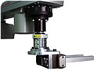
Connected
to the robot wrist, this tool changer enables the robot to change pressroom
tooling automatically. Photo courtesy ATI Industrial Automation.
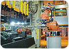
In
this workcell, two robots perform laser cutting to shorten cycle time. Photo
courtesy Reis Robotics USA Inc.
Gaining those seconds (or milliseconds) in cycle time is not easy. “When a workcell is in trouble, very rarely is there a silver bullet,” says Joe Campbell, vice president of sales and marketing for supplier ABB Robotics. “Usually you wind up making several design changes because the engineers had based the initial design on some erroneous assumptions.”
Suppliers also note that cycle times cannot always be shortened. This is usually true for extremely fast or slow applications where fractional time savings are insignificant.
However, for those applications where workcell cycle times can be improved, suppliers suggest the following tips and tricks.
A
simulation tool, like ABB’s RobotStudio, will help determine a robotic system’s
achievable cycle time while it’s still in the design stage. Image courtesy ABB
Robotics.
Six-Axis Robots
Limit robot travel time and distance to and from areas where the actual assembly occurs. This is also true for other types of robots.Realize that the shortest distance between two points might not be a straight line. “Using mostly linear motion rather than joint motion might get the robot from point A to point B most quickly,” says David Alvaro, senior software engineer for Kawasaki Robotics USA Inc. “The opposite is true as well.” To achieve this, assemblers must not worry about the robot’s motion aesthetics.
Use simulation software to predict and validate cycle times, especially those based on maximum output for extended periods of time. Campbell advises both integrators and assemblers to use this type of software, which can predict cycle time to within a couple percentage points.
Know when to sacrifice accuracy for speed. Not all stopping points on a robot’s work path require the same accuracy. Program the robot so it spends more time at points where critical tasks are being done. For example, less precision is required to place an ingot into a forging press, than to grab a semiconductor device and place it in a tester.
Mount the robot to a stiff, solid base with as many joints as necessary. Otherwise the base will flex and put harmonics into the robot itself when it’s moving fast. This will increase the time it takes for the robot to settle at the destination point. Picture a person coming to a stop on a trampoline.
Understand the robot’s performance specifications to extend its operating life. Assemblers need to know the maximum speed at which the robot can be run 24/7 or for short periods of time. Stefan Kissner, project manager for Reis Robotics USA, says assemblers should assume the maximum speed includes a buffer of 10 percent to 20 percent. They also must determine if the specifications are based on the robot working in a hot or cool ambient temperature, or if the temperature is immaterial.
Set the robot’s arm off center at an angle of 180 degrees or more for cutting or welding processes. A robot should start its path program in this position so it can move back to its original orientation without making unnecessary stops after a few curves.
Simplify the robots’ actions by separating motion and nonmotion tasks. Whenever possible, have the robot do all its motion tasks and then all its nonmotion tasks, rather than switching back and forth between the two. All preprocessing should occur before the robot performs any task.
Use robots with a multicommand feature. Some suppliers combine multiple commands into one command. This shortens the time delay between the robot’s movements.
Focus more on the moment of the robot than the payload. “The moment loads on the robot during an application has the potential to cause more damage to the robot and end-effector than payload does,” says Bob Little, COO of ATI Industrial Automation. For example, when a robot picks up a 500-pound payload that is offset, it puts an enormous amount of strain on the end-effector. When the robot accelerates with the load, intertia is added to the force of gravity, significantly increasing the risk of danger to the interface, robot and end-effector.
Correctly apply acceleration. Little says robot acceleration is difficult to calculate, but its correct application can improve cycle time. Assemblers need to be aware that the acceleration of most robots is restricted to five times gravity (5G). They must also be aware of the added danger that may result from increased acceleration.
This
machine assembles electrical connectors using a gripper and rotary swivel heads
with integrated point-of-use valves. Photo courtesy Schunk Inc.
SCARA Robots
Run both joints as close to 100 percent capacity as possible. Doing so will enable the robot to cover more distance faster, says Phil Baratti, application engineering manager for EPSON. Optimum cycle time is achieved by joint one making one-third of the robot’s motion and joint two making two-thirds.To optimize throughput on large works areas, use a robot, such as the RS-SCARA Plus from EPSON, capable of traveling through its work envelope. Because joint two clears joint one, this type of SCARA robot can go through its work envelope rather than around it. The robot’s motion range is 450 degrees on each axis, enabling it to depart or enter a point from any direction.
Lighten tooling and payload wherever possible. Applying this principle to mini SCARA robots can cut cycle times by as much as 0.1 second over a 50-millimeter work area, says Baratti. This tip also applies to six-axis robots.
Use a long-joint robot to cover a longer linear distance faster. On this robot, joint two is longer than joint one and twice as fast. It also has a larger inside working area than standard SCARA robots.
Valves
can be mounted directly to the gripper to improve its response time and enhance
performance of SCARA robots. Photo courtesy PHD Inc.
End-Effectors
Know the robot’s effector capabilities and limitations. Using multiple effectors will increase cycle times, Alvaro says, so be sure to take into account all the latency periods of the devices.Use the smallest effector necessary for an application. Usually, suppliers specify an end-effector that matches the robot’s capacity, says Little. However, when cycle time is a concern, the end-effector can be less than that capacity. For example, a 100-pound effector may be used with a 200-pound-capacity robot.
Place parts to be retrieved as close as possible to the robot. Although it’s easier to design a workcell so that parts are located far from the robot, cycle time will suffer. Equally helpful, the end-effector should be centered under the robot rather than offset in front of it.
Point-of-use valves reduce the gripper’s cycle time. These valves are placed directly into or at the end of an end-effector, and can cut a gripper’s cycle time up to 50 percent, says Jesse Hayes, product manager for automation components at Schunk Inc.
Stack grippers let the robot handle more than one part at a time. The grippers eliminate duplicate traversing by the robot.
Mount a pair of grippers to a rotary actuator for machine-tending applications. A typical application would be placing a part for finishing with one gripper and removing a finished part with another gripper. “Without the swivel heads, the robot would require 5 to 6 seconds to perform these actions,” says Hayes “The heads let the robot do them in 1.5 seconds.”
Activate gripper movements and check for sensor feedback while the robot is traveling to its destination. Don’t wait until after the robot has reached its destination to fully extend or retract the gripper fingers. This can increase cycle time by up to 2 seconds.
Match the flow requirements of the actuator to the application. “Select and size the valve according to the speed of one cycle, not the requirements of one minute,” says Carey Webster, distributor technical services manager for PHD Inc.
Eliminate elbow fittings whenever possible. A 90-degree elbow is equivalent to several feet of tubing, and more tubing increases cycle time, says Webster. Instead, replace the elbow fittings and tubing with straight fittings and standard hose.
Mount the valve as close to the gripper as possible. Webster says mounting pneumatic control valves directly to the gripper decreases response time and gripper open and close time.
Make sure end-of-arm tooling parameters are set correctly. Alvaro says failure to do so may result in the robot not recognizing the tooling and increasing cycle time.
ASSEMBLY Online
For more information on improving cycle time, visit assemblymag.com and search for these articles:Looking for a reprint of this article?
From high-res PDFs to custom plaques, order your copy today!


