Riveting: Forming New Connections
Head-forming technologies are finding applications beyond the automotive assembly line.
In a way, the tough economy has been good for suppliers of assembly technology that have traditionally relied on the automotive industry for the bulk of their business. Forced to pursue alternative markets, suppliers have been invigorated by the challenge of applying current technology to new problems.
At least that’s been the case among suppliers of orbital, radial and roller forming equipment. From a mechanical standpoint, these cold-forming technologies have changed little over the years. What has changed are the assemblies to which they are now being applied. Smaller rivets, exotic materials, greater precision, and more sophisticated tooling are the order of the day.
For example, Todd Hutson, senior applications engineer at Orbitform, never thought his company’s orbital forming equipment would be used on titanium parts for orthopedic implants, but he’s been working on several such applications in recent months. “Titanium is a strange metal to form,” he says. “You just don’t see it much outside the medical device industry.”
Charles A. Rupprecht, executive vice president of BalTec Corp., knows the feeling. “We’re selling to a whole new base of people, and their challenges are a bit different [from those of the automotive industry],” he says. “We’re spending a lot more time in our research lab qualifying the process and developing new tooling.”

Orbital and radial forming are cold-forming processes. There is no impact between the forming tool, or peen, and the post. The principal differences between the two are in the way the tool is driven and in the path it follows on the rivet: around the axis of the rivet in orbital and back and forth through the axis of the rivet in radial.
In orbital riveting, the tool is mounted on a rotating spindle. The axis of the tool is fixed at a 3- to 6-degree angle to the axis of the spindle. As the spindle rotates, the tool orbits the spindle axis and transcribes the pattern of an inverted cone. The tool does not rotate on its own axis. The tool axis intersects the spindle axis at the working end of the tool, and the orbiting tool presses on the post along a radial line that begins at the post’s center.
As forming pressure is applied, a flowing wave of material is formed ahead of the orbiting tool to produce the desired shape. Assemblies can be tightly riveted without damaging the materials being fastened, or as in the case of the orthopedic implant, the post can be formed to allow the parts to pivot.
The head-forming process can take 0.3 second for a thin stud made of a soft material or 2 seconds for a wide stud made of steel. Orbital forming equipment can handle mild steel shanks as large as 1.25 inch or as small as 0.02 inch. With special tooling, orbital forming equipment can swage or flare assemblies exceeding 3 inches in diameter. Multipoint forming on a single workpiece, or gang heading of multiple parts, is also possible.

The peen rotates as the tool is orbiting the rivet. Forming pressure is applied following the rosette pattern, so the pressure line on the peen moves repeatedly through the common centers of the peen and the post. The process of the peen pressing against the post spreads the rivet material radially outward, radially inward and tangentially overlapping.
The main advantage of radial forming is that is does not deform the molecular structure of the metal as much as other riveting processes. It can also form nonround applications, such as a shaft with a single or double D shape, which is often required for high-torque applications.
In orbital and radial forming, the head is formed by a peen attached to a rotating spindle that simultaneously exerts downward force on the workpiece. In roller forming, the peen is replaced with multiple rollers. With the head rotating at 300 to 600 rpm, each pass of the rollers gently pushes and smoothes the material into a seamless, solid form. The rollers intersect the workpiece on a precise contact line, gradually moving material to the desired shape. The process takes about 3 seconds.
The process can form a variety of materials, including brass, copper, cast aluminum, low carbon steel, high carbon steel and stainless steel, explains Hutson. It can be used to form parts ranging in size from 0.25 to 6 inches in diameter.
Because of the additional component of torque, roller forming requires less downward force-as much as 20 percent less-to form a curl or lip than a crimping press. As a result, the process is good for brittle materials, such as cast aluminum, and sensitive assemblies, such as sensors.
There are two types of roller heads: fixed-center heads and articulating heads. A fixed-center head is the most common. It has vertically oriented rollers in set locations.
In contrast, an articulating head has a set of three horizontally oriented rollers mounted to fingers that move in unison like the jaws of a robotic gripper. The fingers move the rollers into the piece being formed while applying a clamp load to the assembly. This type of head is useful if parts of the assembly protrude above the center bore. When equipped with an additional set of vertically adjustable interior rollers, an articulated head can simultaneously form the outside and inside diameters of a workpiece.
The number of rollers on the head depends on the thickness and material of the part and how much force will be applied, says Hutson. Three rollers are most commonly used. Only two rollers might be necessary for a small part, while a very large part may require five.
Whether fixed or articulated, each roller and roller head assembly is custom-made to suit a specific application. However, roller heads are easily swapped out. Indeed, the same base machine can perform both orbital forming and roller forming. And, like orbital and radial forming, roller forming can be done as a standalone, semiautomatic process or integrated into a fully automatic assembly system.
The key variables of the process are downward force, torque, rotational speed, time and stroke. These settings will vary depending on part size, material, and joint strength requirements. “Our applications lab can provide guidance on the optimal parameters, as well as design guidelines for the preform geometry of the parts,” says Hutson. “You want the material to follow the path of least resistance, and you don’t want it to move any farther than necessary to secure the joint.”
Roller forming has been used on myriad assemblies, including solenoids, cam followers, ball joints, tie-rods, air bag components, manifolds for antilock brake systems, fuses and even colored filters for stage lights. “One of our customers uses roller forming to secure a bearing inside the cast aluminum housing for a water pump,” says Hutson. “The company had been using a snap ring to secure the bearing. Roller forming produced a stronger joint and saved the cost of the ring and the time and expense of machining a groove for it. The company has a shelf full of roller heads for different pumps.”
“Once you determine the forming parameters for a good part, you can establish tolerance bands for each variable,” explains Rupprecht. “If the process falls outside of those tolerances, the machine will alert the operator that a bad part has been made.”
Although process monitoring has been around for a few years now, suppliers have made great strides in making the technology more user-friendly. For example, BalTec’s new HPP-25 controller enables engineers to stop the forming process in response to an external signal or upon reaching any of the following values: forming distance, riveting time, riveting force, total travel of the riveting spindle, and closing head height. The controller offers a choice of 39 riveting modes with different, monitored control values.
All riveting data can be recorded by an integrated data-logging program tool and viewed, analyzed and exported using a 5.7-inch touch-screen. Data can be exported and imported to a PC via USB and Ethernet interfaces. Parameters and riveting programs can be uploaded and downloaded for backup purposes. An error history can be exported to facilitate in-field diagnostics and support.
“You can download your programs and send them to us. We can analyze them in our application lab and send a new program back to you. You can put that program on a USB memory stick and instantly reprogram your machine,” says Rupprecht.
In a way, the tough economy has been good for suppliers of assembly technology that have traditionally relied on the automotive industry for the bulk of their business. Forced to pursue alternative markets, suppliers have been invigorated by the challenge of applying current technology to new problems.
At least that’s been the case among suppliers of orbital, radial and roller forming equipment. From a mechanical standpoint, these cold-forming technologies have changed little over the years. What has changed are the assemblies to which they are now being applied. Smaller rivets, exotic materials, greater precision, and more sophisticated tooling are the order of the day.
For example, Todd Hutson, senior applications engineer at Orbitform, never thought his company’s orbital forming equipment would be used on titanium parts for orthopedic implants, but he’s been working on several such applications in recent months. “Titanium is a strange metal to form,” he says. “You just don’t see it much outside the medical device industry.”
Charles A. Rupprecht, executive vice president of BalTec Corp., knows the feeling. “We’re selling to a whole new base of people, and their challenges are a bit different [from those of the automotive industry],” he says. “We’re spending a lot more time in our research lab qualifying the process and developing new tooling.”
Orbital Forming
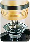
The chief advantage of orbital and radial forming is that they eliminate loose fasteners from an assembly in favor of posts or ridges that are cast or machined in one of the parts. The mating part slips over these protrusions, which are then flared out to complete the assembly.Orbital and radial forming are cold-forming processes. There is no impact between the forming tool, or peen, and the post. The principal differences between the two are in the way the tool is driven and in the path it follows on the rivet: around the axis of the rivet in orbital and back and forth through the axis of the rivet in radial.
In orbital riveting, the tool is mounted on a rotating spindle. The axis of the tool is fixed at a 3- to 6-degree angle to the axis of the spindle. As the spindle rotates, the tool orbits the spindle axis and transcribes the pattern of an inverted cone. The tool does not rotate on its own axis. The tool axis intersects the spindle axis at the working end of the tool, and the orbiting tool presses on the post along a radial line that begins at the post’s center.
As forming pressure is applied, a flowing wave of material is formed ahead of the orbiting tool to produce the desired shape. Assemblies can be tightly riveted without damaging the materials being fastened, or as in the case of the orthopedic implant, the post can be formed to allow the parts to pivot.
The head-forming process can take 0.3 second for a thin stud made of a soft material or 2 seconds for a wide stud made of steel. Orbital forming equipment can handle mild steel shanks as large as 1.25 inch or as small as 0.02 inch. With special tooling, orbital forming equipment can swage or flare assemblies exceeding 3 inches in diameter. Multipoint forming on a single workpiece, or gang heading of multiple parts, is also possible.
Radial Forming
Like orbital forming, the radial process produces heads on rivets and posts. However, with radial forming, the peen axis is not held at a fixed angle with the spindle axis. The working end of the peen passes over the end of the post on a path that is an 11-loop rosette. The angle between the peen axis and spindle axis varies continuously between 0 to 6 degrees. The angle between the two is 0 degrees when the axes are aligned.The peen rotates as the tool is orbiting the rivet. Forming pressure is applied following the rosette pattern, so the pressure line on the peen moves repeatedly through the common centers of the peen and the post. The process of the peen pressing against the post spreads the rivet material radially outward, radially inward and tangentially overlapping.
The main advantage of radial forming is that is does not deform the molecular structure of the metal as much as other riveting processes. It can also form nonround applications, such as a shaft with a single or double D shape, which is often required for high-torque applications.
Roller Forming
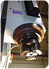
A variant of orbital and radial forming is roller forming. Like orbital and radial forming, roller forming is a nonimpact process for cold-forming metal. However, instead of forming a head on a post or a rivet, the process forms a curl or lip on the edge or rim of a hollow, cylindrical part. This can be done to secure a part, such as a bearing, inside another part, or it can simply be used to finish the ends of a metal tube to make it safer, improve cosmetics or facilitate insertion of the tube into another part.In orbital and radial forming, the head is formed by a peen attached to a rotating spindle that simultaneously exerts downward force on the workpiece. In roller forming, the peen is replaced with multiple rollers. With the head rotating at 300 to 600 rpm, each pass of the rollers gently pushes and smoothes the material into a seamless, solid form. The rollers intersect the workpiece on a precise contact line, gradually moving material to the desired shape. The process takes about 3 seconds.
The process can form a variety of materials, including brass, copper, cast aluminum, low carbon steel, high carbon steel and stainless steel, explains Hutson. It can be used to form parts ranging in size from 0.25 to 6 inches in diameter.
Because of the additional component of torque, roller forming requires less downward force-as much as 20 percent less-to form a curl or lip than a crimping press. As a result, the process is good for brittle materials, such as cast aluminum, and sensitive assemblies, such as sensors.
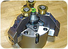
There are two types of roller heads: fixed-center heads and articulating heads. A fixed-center head is the most common. It has vertically oriented rollers in set locations.
In contrast, an articulating head has a set of three horizontally oriented rollers mounted to fingers that move in unison like the jaws of a robotic gripper. The fingers move the rollers into the piece being formed while applying a clamp load to the assembly. This type of head is useful if parts of the assembly protrude above the center bore. When equipped with an additional set of vertically adjustable interior rollers, an articulated head can simultaneously form the outside and inside diameters of a workpiece.
The number of rollers on the head depends on the thickness and material of the part and how much force will be applied, says Hutson. Three rollers are most commonly used. Only two rollers might be necessary for a small part, while a very large part may require five.
Whether fixed or articulated, each roller and roller head assembly is custom-made to suit a specific application. However, roller heads are easily swapped out. Indeed, the same base machine can perform both orbital forming and roller forming. And, like orbital and radial forming, roller forming can be done as a standalone, semiautomatic process or integrated into a fully automatic assembly system.
The key variables of the process are downward force, torque, rotational speed, time and stroke. These settings will vary depending on part size, material, and joint strength requirements. “Our applications lab can provide guidance on the optimal parameters, as well as design guidelines for the preform geometry of the parts,” says Hutson. “You want the material to follow the path of least resistance, and you don’t want it to move any farther than necessary to secure the joint.”
Roller forming has been used on myriad assemblies, including solenoids, cam followers, ball joints, tie-rods, air bag components, manifolds for antilock brake systems, fuses and even colored filters for stage lights. “One of our customers uses roller forming to secure a bearing inside the cast aluminum housing for a water pump,” says Hutson. “The company had been using a snap ring to secure the bearing. Roller forming produced a stronger joint and saved the cost of the ring and the time and expense of machining a groove for it. The company has a shelf full of roller heads for different pumps.”
Process Monitoring
Over the past few years, all three forming technologies have benefited significantly from the same sensing technologies that have given assemblers so much control over ultrasonic welding, press-fitting and other force-dependent processes. Thanks to sensors and some sophisticated software, assemblers can measure and control the three key variables in the forming process: force, time and stroke.“Once you determine the forming parameters for a good part, you can establish tolerance bands for each variable,” explains Rupprecht. “If the process falls outside of those tolerances, the machine will alert the operator that a bad part has been made.”
Although process monitoring has been around for a few years now, suppliers have made great strides in making the technology more user-friendly. For example, BalTec’s new HPP-25 controller enables engineers to stop the forming process in response to an external signal or upon reaching any of the following values: forming distance, riveting time, riveting force, total travel of the riveting spindle, and closing head height. The controller offers a choice of 39 riveting modes with different, monitored control values.
All riveting data can be recorded by an integrated data-logging program tool and viewed, analyzed and exported using a 5.7-inch touch-screen. Data can be exported and imported to a PC via USB and Ethernet interfaces. Parameters and riveting programs can be uploaded and downloaded for backup purposes. An error history can be exported to facilitate in-field diagnostics and support.
“You can download your programs and send them to us. We can analyze them in our application lab and send a new program back to you. You can put that program on a USB memory stick and instantly reprogram your machine,” says Rupprecht.
Looking for a reprint of this article?
From high-res PDFs to custom plaques, order your copy today!


