Automation Profiles: System Assembles Family of Car Latches
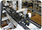
Each pallet holds one latch assembly and carries a small, passive RFID tag. A read-write head at each station updates the status of each assembly. If an assembly fails a check at any station, it will pass subsequent stations without receiving any more value. Photo courtesy Eastern Automation Systems
A case in point is an asynchronous system designed by Eastern Automation Systems (Farmingdale, NJ). The system automatically assembles a family of 13 automotive interior latches. A pallet-transfer conveyor, configured in an 8-foot by 20-foot loop, shuttles assemblies through 13 stations. A manual station is also included to handle future styles that cannot be accommodated by the automatic feeders.
In this profile, Scott Bellows, CMfgE, president of Eastern Automation, describes how the system works. For more information, call 732-938-2002 or visit www.easternautomation.net.

The latch consists of seven parts, plus a dab of silicone grease. The parts are a lock member (1), hous-ing (2), bumper (3), silicone grease (4), compression spring (5), pawl (6), handle (7)-four styles shown-and headed pin (8). Photo courtesy Eastern Automation Systems
What are the parts made of? The four plastic pieces are glass-filled nylon. The shock bumper is rubber. There are two metal parts. One is a compression spring; the other is a headed steel pin.
What feeds the parts? Seven vibratory feeders. All the feeders are equipped with vibratory, inline feed tracks, and five have vibratory bulk-feed hoppers. This arrangement ensures long intervals between parts replenishment.
What is the production rate? 700 latches per hour.
What checks are included? Part presence is detected in each station using various devices. At one station, a photoelectric sensor is aimed specifically at the “short shot” locations on the injection-molded parts. This doubles the value of each check by enabling detection of both missing and incompletely molded parts.
The system has 40 custom-tooled pallets. Each pallet holds one latch assembly and carries a small, passive RFID tag. An RFID read-write head at each station updates the status of each assembly. If an assembly fails an inspection at any point, the pallet will be passed along without further value-adding operations, and its cargo will be off-loaded at a reject station. This increases the production rate of good assemblies.
Describe each assembly station. At station 1, a lock member is added to the pallet-but only for assemblies that include the locking feature. A vibratory feeder, a pneumatic pick-and-place unit, and a pneumatic gripper transfer the component.
At station 2, a housing is added. The pallet tooling locates the lock member to the housing. A vibratory feeder, a pick-and-place unit, and a gripper transfer the component.
At station 3, a bumper is added. A vibratory feeder, a pick-and-place unit, and an end-of-arm insertion pin with vacuum tooling press the bayonet end of the bumper into the housing. After assembly, the bumper is scanned with a photoelectric sensor. The sensor determines if the bumper is missing, too high or “just right.”
At station 4, a pea-sized drop of dense silicone grease is applied inside the housing where the spring will rest. Using a pneumatic guide unit, a dispensing head, and a quick-change grease cartridge, the right amount of grease is added. Because an ungreased part would constitute a “bad” assembly, the drop of grease is verified present with a laser sensor.
At station 5, a compression spring is inserted. A vibratory feeder with a pneumatic escapement is used to insert the spring onto the pallet. A high-strength magnet in the pallet tooling keeps the spring proud for the next operation. The spring has three dead coils in the middle. Without this feature, the springs would be hard to feed.
At station 6, a pawl is placed on a guide track on the pallet for later insertion. A vibratory feeder, a pick-and-place unit, and a gripper assemble the pawl.
At station 7, a latch handle is placed in position. The handle holds the pawl in the housing until the assembly can be completed at the next station. Two vibratory feeders, a pick-and-place unit, a pneumatic rotator, and quick-change vacuum cup tooling accomplish this task.
At station 8, a headed steel pin is installed. A vibratory feeder, a gripper and a custom pneumatic press are used to insert the pin. The pin secures all the parts into a complete assembly.
At station 9, latch functionality is tested. A pneumatic slide actuates the latch, while a load cell records the force necessary to actuate the handle. This data is compared against pass-fail criteria.
At station 10, RGB color sensors check the handle to make sure it’s the right color.
At station 11, assemblies that failed any checks are off-loaded into a reject bin.
At station 12, assemblies that satisfied all quality checks and assembly cycles are off-loaded to a packing conveyor.
Looking for a reprint of this article?
From high-res PDFs to custom plaques, order your copy today!


