Lead-Free Soldering by Hand
A new soldering iron technology enhances joint quality, improves process stability, and lowers operational costs for manual lead-free soldering.
 Now that lead-free electronics assembly is a fact of life, rework has emerged as a significant challenge. Long considered to be the weakest link in lead-free assembly, manual soldering requires rigorous process control.
The challenge of lead-free soldering is two-fold. Lead-free alloys require higher process temperatures than traditional alloys. At the same time, the thermal threshold of today’s electronic components is narrower than before. As a result, thermal stability and repeatability are critical for rework with lead-free solder.
According to a recent study, manual soldering was found to be more problematic to convert to a lead-free process than wave soldering and reflow soldering. Poor wetting and cold solder joints can occur with low tip temperatures or insufficient flux activation. On the other hand, excessive tip temperatures cause dewetting and thermal damage to circuit boards and components. Maintaining the correct tip temperature with adequate, but not excessive, heat transfer is essential for creating reliable joints.
Because manual soldering is an operator-dependent process, poorly equipped and poorly trained technicians will be incapable of making the jump to lead-free. By some estimates, only 10 percent to 25 percent of electronics assembly companies have taken advantage of IPC-certified training in manual soldering. Most companies simply buy soldering irons and turn them over to line personnel.
This trend has been a boon to third-party rework providers, who are deluged with desperate phone calls from assemblers complaining of lifted pads and thermal damage. Frequently, assemblers ask for the damage be repaired, but fail to address the cause of the problem. Management will eventually take notice when the problem affects the bottom line.
Temperature, however, is governed by the actual temperature of the tip during soldering, and that depends entirely on the design of the soldering iron. With some soldering irons, the temperature often overshoots the ideal thermal profile, or the operator fails to dwell for sufficient time. Either error can result in inadequate solder joint formation and should be eliminated.
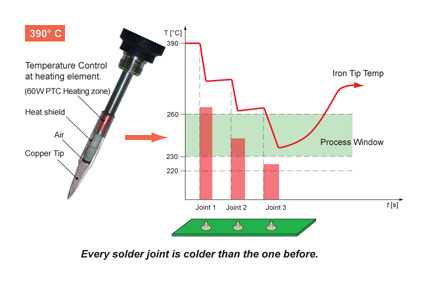
Joint temperature is determined by how well a soldering iron recovers heat lost at the tip, as well as by how long the tip remains on the joint. In some soldering irons, the thermal sensor is located far from the tip. The tip loses temperature into the joints, but can’t recover fast enough before the next joint is made. As a result, each consecutive solder joint could be colder than the previous one.
Today’s irons perform much better. In most of these, however, the tip is attached directly to the heating element cartridge. There are two problems with this design. First, the tip can overshoot the desired temperature. Second, the cost of replacing the tip can be excessive. Such irons force companies to throw away perfectly good and expensive heating elements simply because the small copper tip is worn out. Tip consumption will be higher with lead-free soldering, so concern about the replacement cost and longevity of solder tips is critical.
A new soldering iron developed by ERSA addresses these issues. The i-Tool has a 150-watt micro heating element that provides more consistent performance compared with soldering irons equipped with heating element cartridges. In addition, the tips can be exchanged without replacing the heating element at the same time, which saves money. Savings can be as much as seven times greater with exchangeable tips than cartridge tips, when compared on a per station basis.
The tip heats from room temperature to 350 C in approximately 9 seconds, and it goes from standby temperature to 350 C in only 3 seconds. The iron recovers heat so fast that all solder joints can be made at nearly the same temperature. A sensor measures the temperature very close to the tip extremity.
The i-Tool is also equipped with an electronic motion sensor that recognizes when the iron is being used. The iron automatically goes into a lower standby temperature when the iron is put into its holder or is no longer moving. Some control stations accomplish the same task using a micro switch in the holder. However, if the iron is not placed in exactly the right position, the switch may not work.
A unique feature of the new soldering iron is a process window alarm that visually and audibly notifies operators when the tip temperature is outside a specified range, ensuring temperature control and process stability.
The microprocessor for calibrating the soldering iron is located on a circuit board embedded in the tool’s handle. This allows each iron to be calibrated independently of the control station, which saves time and money. Only the irons need to be taken for centralized calibration, which is easier and requires less production downtime.
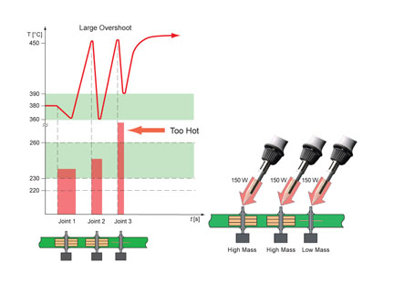
For most soldering irons, this dichotomy has meant a compromise between power and control. Irons that recover rapidly on high-mass joints can experience large temperature overshoots, damaging temperature-sensitive components. The i-Tool avoids this problem by allowing the operator to balance power and control. The operator can choose from three power settings for the heating element, depending on the heat required for the application. At the high power level, the iron uses 100 percent of its 150 watts, delivering maximum heat and enabling rapid soldering of high-mass joints. The low-level setting holds back heat to prevent overshoot for sensitive applications. The medium power level is a balance between these two conditions.
As a result, tips for lead-free soldering have thicker iron plating than standard tips. However, this does not obviate the need to keep the tip tinned. When working with lead-free solder, retinning must be conducted more frequently.
Another factor adversely affecting tip life is related to how operators solder joints. Many operators press harder while soldering with lead-free alloys, thinking they are transferring more heat. In fact, additional pressure does not improve heat transfer, but it does result in cracking and pitting of the iron plating and hastens degradation of the tip, exposing the copper core and shortening solder tip life.
As a result, retraining is recommended for operators as well as inspectors. Most inspectors should revisit acceptance criteria set forth in IPC-A-610D. They should also review industry standards for grainy solder joints, contact angle and other subjects. A significant benefit of retraining is a reduction in needless repair work. Diminishing the subjective nature of manual inspection will significantly reduce the unnecessary touch-up of solder joints that would normally be acceptable.
An effective retraining program can be implemented with a multitiered solder skills assessment and retraining curriculum. This process consists of three steps:
1. Awareness Phase. Assemblers must be cognizant of the financial cost of manufacturing defects and their detrimental impact on customer relationships.
2. Audit and Assessment Phase. Managers should conduct an on-site, shoulder-to-shoulder appraisal of the knowledge and skills of assemblers and inspectors.
3. Training Phase. Assemblers and inspectors are retrained. Topics should include:
The challenge of lead-free soldering is two-fold. Lead-free alloys require higher process temperatures than traditional alloys. At the same time, the thermal threshold of today’s electronic components is narrower than before. As a result, thermal stability and repeatability are critical for rework with lead-free solder.
According to a recent study, manual soldering was found to be more problematic to convert to a lead-free process than wave soldering and reflow soldering. Poor wetting and cold solder joints can occur with low tip temperatures or insufficient flux activation. On the other hand, excessive tip temperatures cause dewetting and thermal damage to circuit boards and components. Maintaining the correct tip temperature with adequate, but not excessive, heat transfer is essential for creating reliable joints.
Management Awareness
Three things are necessary for quality lead-free soldering by hand: capable soldering tools, sufficient operator training, and management focus on the importance of the manual rework process. Senior management should focus on every step of their electronics assembly operations, of course. More often than not, however, managers devote their attention to areas of major capital investment, such as screen printing, placement, reflow, test and inspection. Manual soldering is overlooked. Decisions about soldering tools and operator training are relegated to lower level personnel. This oversight is an invitation to disaster.Because manual soldering is an operator-dependent process, poorly equipped and poorly trained technicians will be incapable of making the jump to lead-free. By some estimates, only 10 percent to 25 percent of electronics assembly companies have taken advantage of IPC-certified training in manual soldering. Most companies simply buy soldering irons and turn them over to line personnel.
This trend has been a boon to third-party rework providers, who are deluged with desperate phone calls from assemblers complaining of lifted pads and thermal damage. Frequently, assemblers ask for the damage be repaired, but fail to address the cause of the problem. Management will eventually take notice when the problem affects the bottom line.
In some soldering irons, the thermal sensor is located far from the tip. The tip loses temperature into the joints, but can’t recover fast enough before the next joint is made. As a result, each consecutive solder joint could be colder than the previous one.
Thermal Stability
A repeatable and stable manual soldering process depends on three factors: time, temperature and technique. Time-or the dwell time of the soldering iron tip on the joint-and technique depend on operator skill. Because most lead-free alloys exhibit poor wetting characteristics and slow wetting times compared with tin-lead solder, an elongated dwell time is recommended.Temperature, however, is governed by the actual temperature of the tip during soldering, and that depends entirely on the design of the soldering iron. With some soldering irons, the temperature often overshoots the ideal thermal profile, or the operator fails to dwell for sufficient time. Either error can result in inadequate solder joint formation and should be eliminated.
Joint temperature is determined by how well a soldering iron recovers heat lost at the tip, as well as by how long the tip remains on the joint. In some soldering irons, the thermal sensor is located far from the tip. The tip loses temperature into the joints, but can’t recover fast enough before the next joint is made. As a result, each consecutive solder joint could be colder than the previous one.
Today’s irons perform much better. In most of these, however, the tip is attached directly to the heating element cartridge. There are two problems with this design. First, the tip can overshoot the desired temperature. Second, the cost of replacing the tip can be excessive. Such irons force companies to throw away perfectly good and expensive heating elements simply because the small copper tip is worn out. Tip consumption will be higher with lead-free soldering, so concern about the replacement cost and longevity of solder tips is critical.
A new soldering iron developed by ERSA addresses these issues. The i-Tool has a 150-watt micro heating element that provides more consistent performance compared with soldering irons equipped with heating element cartridges. In addition, the tips can be exchanged without replacing the heating element at the same time, which saves money. Savings can be as much as seven times greater with exchangeable tips than cartridge tips, when compared on a per station basis.
The tip heats from room temperature to 350 C in approximately 9 seconds, and it goes from standby temperature to 350 C in only 3 seconds. The iron recovers heat so fast that all solder joints can be made at nearly the same temperature. A sensor measures the temperature very close to the tip extremity.
The i-Tool is also equipped with an electronic motion sensor that recognizes when the iron is being used. The iron automatically goes into a lower standby temperature when the iron is put into its holder or is no longer moving. Some control stations accomplish the same task using a micro switch in the holder. However, if the iron is not placed in exactly the right position, the switch may not work.
A unique feature of the new soldering iron is a process window alarm that visually and audibly notifies operators when the tip temperature is outside a specified range, ensuring temperature control and process stability.
The microprocessor for calibrating the soldering iron is located on a circuit board embedded in the tool’s handle. This allows each iron to be calibrated independently of the control station, which saves time and money. Only the irons need to be taken for centralized calibration, which is easier and requires less production downtime.
Each time an iron’s tip touches a lead, heat is conducted into the joint, requiring the heating element to power up to replace the heat loss. When the tip is removed, heat energy continues to flow for an instant. With an iron equipped with a heating element cartridge, this can lead to a temperature overshoot as high as 80 to 100 C.
Temperature Overshoot
Each time an iron’s tip touches a lead, heat is conducted into the joint, requiring the heating element to power up to replace the heat loss. When the tip is removed from the joint, heat energy continues to flow for an instant, as if the mass of the joint were still present. With an iron equipped with a heating element cartridge, this can lead to a temperature overshoot at the tip as high as 80 to 100 C. For many sensitive components, and for military and medical applications, this is unacceptable. Conversely, to solder a heavy through-hole component on a multilayer board, or a heat shield on a regular board, the iron needs all the power available from the heating element to transfer enough heat.For most soldering irons, this dichotomy has meant a compromise between power and control. Irons that recover rapidly on high-mass joints can experience large temperature overshoots, damaging temperature-sensitive components. The i-Tool avoids this problem by allowing the operator to balance power and control. The operator can choose from three power settings for the heating element, depending on the heat required for the application. At the high power level, the iron uses 100 percent of its 150 watts, delivering maximum heat and enabling rapid soldering of high-mass joints. The low-level setting holds back heat to prevent overshoot for sensitive applications. The medium power level is a balance between these two conditions.
Operational Costs
Periodic replacement of iron tips is a major expense with manual lead-free soldering. Most lead-free alloys have significantly more tin than their lead-bearing counterparts. Lead-free alloys quickly erode the iron plating on tips, due to the aggressive nature of tin at high temperature. The surface of the tip will become pitted and corroded, as the iron plating leaches into the molten tin. Over time, this erosion degrades the thermal performance of the tip and adversely affects its ability to conduct heat.As a result, tips for lead-free soldering have thicker iron plating than standard tips. However, this does not obviate the need to keep the tip tinned. When working with lead-free solder, retinning must be conducted more frequently.
Another factor adversely affecting tip life is related to how operators solder joints. Many operators press harder while soldering with lead-free alloys, thinking they are transferring more heat. In fact, additional pressure does not improve heat transfer, but it does result in cracking and pitting of the iron plating and hastens degradation of the tip, exposing the copper core and shortening solder tip life.
Sidebar: Soldering Skills Assessment
When soldering joints manually, operators and inspectors should remember two key facts. First, lead-free alloys are not as forgiving as tin-lead solder. Second, lead-free joints differ visually from tin-lead joints. Marginally trained operators who can solder adequately with tin-lead alloys typically have difficulty with lead-free alloys. The result is an increase in damage to boards and components.As a result, retraining is recommended for operators as well as inspectors. Most inspectors should revisit acceptance criteria set forth in IPC-A-610D. They should also review industry standards for grainy solder joints, contact angle and other subjects. A significant benefit of retraining is a reduction in needless repair work. Diminishing the subjective nature of manual inspection will significantly reduce the unnecessary touch-up of solder joints that would normally be acceptable.
An effective retraining program can be implemented with a multitiered solder skills assessment and retraining curriculum. This process consists of three steps:
1. Awareness Phase. Assemblers must be cognizant of the financial cost of manufacturing defects and their detrimental impact on customer relationships.
2. Audit and Assessment Phase. Managers should conduct an on-site, shoulder-to-shoulder appraisal of the knowledge and skills of assemblers and inspectors.
3. Training Phase. Assemblers and inspectors are retrained. Topics should include:
- Assembly requirements.
- Acceptance criteria.
- Soldering and desoldering tools.
- Lighting, magnification and fume extraction.
- Static-discharge prevention.
Looking for a reprint of this article?
From high-res PDFs to custom plaques, order your copy today!


