Using the Right Tool
The right tool for the right job: The old adage holds true for machine vision and parts tracking, the same as it does for anything else in manufacturing.
An aircraft engine manufacturer, for example, recently found it had a number of conditions it needed to meet if it was to automate the manual documentation system it used to track the thousands of components making up each of its engines-in compliance with the requirements mandated by “Air Transport Association SPEC 2000.”
The new automated tracking systems employs 2D Data Matrix codes imprinted on each part using a percussive dot-peen method. Because this method relies on small changes in depth to create the light and dark areas of the code-as opposed to contrasting colors-the imaging system needed to be both robust and sensitive to avoid reading errors. In addition, because the parts involved range in size from small metal tubes to large fan blades, the company needed a wireless system that would enable operators to move around a part to access the code-instead of having to maneuver the part closer to the scanner.
As a result the company went with a series of MS-Q handheld imagers, which feature wireless communication at a range of up to 300 feet. The MS-Q is also capable of reading low-contrast dot peen codes under challenging lighting conditions and was easy to integrate into the company’s designated tracking system.
 The right tool for the right job: The old adage holds true for machine vision and parts tracking, the same as it does for anything else in manufacturing.
An aircraft engine manufacturer, for example, recently found it had a number of conditions it needed to meet if it was to automate the manual documentation system it used to track the thousands of components making up each of its engines-in compliance with the requirements mandated by “Air Transport Association SPEC 2000.”
The new automated tracking system employs 2D Data Matrix codes imprinted on each part using a percussive dot-peen method. Because this method relies on small changes in depth to create the light and dark areas of the code-as opposed to contrasting colors-the imaging system needed to be both robust and sensitive to avoid reading errors. In addition, because the parts involved range in size from small metal tubes to large fan blades, the company needed a wireless system that would enable operators to move around a part to access the code-instead of having to maneuver the part closer to the scanner.
As a result the company went with a series of MS-Q handheld imagers, which feature wireless communication at a range of up to 300 feet. The MS-Q is also capable of reading low-contrast dot peen codes under challenging lighting conditions and was easy to integrate into the company’s designated tracking system.

Once again, it was the Quadras EZ’s ability to compensate for changes in ambient lighting and fluctuations in symbol contrast that made it the system of choice. The difference in this case is that each camera operates from a fixed location, instead of being handheld.
Because the Quadrus EZ can read the symbols at normal production line speeds, the manufacturer is able to track all of its brake components without in any way slowing production. This has allowed the company to manage repairs and recalls more efficiently by allowing it to identify and recall only those specific vehicles with a faulty part, as opposed to all those vehicles equipped with a particular model of brake.
To accommodate these requirements, the company installed a number of MS-880 readers on a series of posts built alongside its production line. Each MS-880 reader’s laser is programmed as a static line, which crosses the conveyor at a 45-degree angle and reads the bar codes on each engine block at a distance of approximately 48 inches. Because the MS-880 has an extended read range of more than 7.5 feet, it has no trouble reading the codes at the company’s targeted production speeds. In fact, the company has since been able to increase its production rate.
As an added benefit, the MS-880’s “sweeping programmable raster” feature allows it to read the codes no matter where a particular engine may be located on the conveyor. For more information on these and other machine vision applications, www.microscan.com.
An aircraft engine manufacturer, for example, recently found it had a number of conditions it needed to meet if it was to automate the manual documentation system it used to track the thousands of components making up each of its engines-in compliance with the requirements mandated by “Air Transport Association SPEC 2000.”
The new automated tracking systems employs 2D Data Matrix codes imprinted on each part using a percussive dot-peen method. Because this method relies on small changes in depth to create the light and dark areas of the code-as opposed to contrasting colors-the imaging system needed to be both robust and sensitive to avoid reading errors. In addition, because the parts involved range in size from small metal tubes to large fan blades, the company needed a wireless system that would enable operators to move around a part to access the code-instead of having to maneuver the part closer to the scanner.
As a result the company went with a series of MS-Q handheld imagers, which feature wireless communication at a range of up to 300 feet. The MS-Q is also capable of reading low-contrast dot peen codes under challenging lighting conditions and was easy to integrate into the company’s designated tracking system.
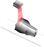
An aircraft manufacturer needed a wireless system that would enable operators to move around a part to access the codes.
An aircraft engine manufacturer, for example, recently found it had a number of conditions it needed to meet if it was to automate the manual documentation system it used to track the thousands of components making up each of its engines-in compliance with the requirements mandated by “Air Transport Association SPEC 2000.”
The new automated tracking system employs 2D Data Matrix codes imprinted on each part using a percussive dot-peen method. Because this method relies on small changes in depth to create the light and dark areas of the code-as opposed to contrasting colors-the imaging system needed to be both robust and sensitive to avoid reading errors. In addition, because the parts involved range in size from small metal tubes to large fan blades, the company needed a wireless system that would enable operators to move around a part to access the code-instead of having to maneuver the part closer to the scanner.
As a result the company went with a series of MS-Q handheld imagers, which feature wireless communication at a range of up to 300 feet. The MS-Q is also capable of reading low-contrast dot peen codes under challenging lighting conditions and was easy to integrate into the company’s designated tracking system.
The Quadras EZ’s ability to compensate for changes in ambient lighting and fluctuations in symbol contrast made it the system of choice.
Tracking Brake Components
Along these same lines, an anti-lock brake manufacturer needed an imager to help it track the various components making up its products, which are also percussion-marked with 2D dot-peen codes. To do so, it installed a series of Quadrus EZ smart cameras at a number of different stations along its assembly lines. At each station, the cameras read the code and the data is sent to a host system, which verifies that the part has been added to the assembly before the assembly is passed to the next processing station.Once again, it was the Quadras EZ’s ability to compensate for changes in ambient lighting and fluctuations in symbol contrast that made it the system of choice. The difference in this case is that each camera operates from a fixed location, instead of being handheld.
Because the Quadrus EZ can read the symbols at normal production line speeds, the manufacturer is able to track all of its brake components without in any way slowing production. This has allowed the company to manage repairs and recalls more efficiently by allowing it to identify and recall only those specific vehicles with a faulty part, as opposed to all those vehicles equipped with a particular model of brake.
Because the MS-880 has an extended read range of more than 7.5 feet, it has no trouble reading the codes at the company’s targeted production speeds.
Keeping up with Production
Finally, to maximize throughput, an engine manufacturer needed a scanner that could read the bar codes on its engine blocks without requiring a line stop for each read. In this case, the manufacturer was using a black-on-white thermal transfer bar code applied to the top of the engine.To accommodate these requirements, the company installed a number of MS-880 readers on a series of posts built alongside its production line. Each MS-880 reader’s laser is programmed as a static line, which crosses the conveyor at a 45-degree angle and reads the bar codes on each engine block at a distance of approximately 48 inches. Because the MS-880 has an extended read range of more than 7.5 feet, it has no trouble reading the codes at the company’s targeted production speeds. In fact, the company has since been able to increase its production rate.
As an added benefit, the MS-880’s “sweeping programmable raster” feature allows it to read the codes no matter where a particular engine may be located on the conveyor. For more information on these and other machine vision applications, www.microscan.com.
Looking for a reprint of this article?
From high-res PDFs to custom plaques, order your copy today!