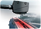
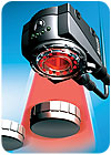
New technology bridges the gap between simple sensors and full-blown vision systems.

Years ago, manufacturers relied on PLCs to handle many quality-related tasks. Today, assemblers depend on sensors and vision systems to ensure their products are in spec. The next step forward in quality management may well be the merger of sensor and vision technologies.
On many assembly lines, error-proofing sensors, such as photoelectric, inductive and laser sensors, are an integral part of the manufacturing process. These simple, inexpensive sensors provide discrete outputs (yes or no, present or absent) or analog outputs (specific measurements). Discrete sensors are easy to integrate, while analog sensors convey actual data on the length, width, height or position of a feature, part or assembly. Outputs from either sensor can interface directly with control systems to pause a machine, redirect a part, or signal an operator.
Error-proofing sensors can be deployed at each assembly station to prevent out-of-spec parts from reaching the next station. This type of error-proofing works best when the parts are automatically positioned for inspection in exactly the same way. In this way, each sensor can be aimed to verify a specific aspect of the part that indicates a manufacturing step has been done correctly. In effect, each sensor performs an individual mini inspection on the part as it passes by.
For example, a laser sensor can verify that a bead of adhesive has been dispensed onto a part. The laser beam is aimed above the part surface, but below the maximum height of the adhesive. If the beam is interrupted as the part passes the sensor, the adhesive must be present. Similarly, a photoelectric sensor can be used to error-proof a stamping operation. To prevent damage to the die, it’s critical to ensure that a freshly stamped part has left the die before the next actuation of the press. The problem is solved by placing a photoelectric sensor at the end of the exit chute. If the sensor is tripped at the end of a stamping cycle, the part must be clear and the press can actuate again.
Inspection with a machine vision system typically requires more expensive equipment and is designed to mimic the old-fashioned, end-of-the-line final inspection. On the other hand, a vision system can inspect parts in various attitudes relative to the camera, and it can check more than one attribute simultaneously. For example, it can simultaneously check an assembly for the presence or absence of a feature; ensure that a part is correctly oriented; measure various part dimensions; and verify that a part is the correct color.
Sensors and vision systems tend to be polar opposites in terms of complexity and capability. Sensors are excellent for discrete manufacturing operations. They are an inexpensive error-proofing technology, as long as the parameters to be checked can be handled by a limited number of sensors. On the opposite end of the spectrum, machine vision systems are ideal for complex, multitasking inspection routines.
This leaves a gap in inspection technology. Both sensors and vision systems can be used to inspect parts and error-proof assembly processes. But, some applications are too complex to be checked with a sensor, and too simple to justify the cost or complexity of a vision system.
To bridge that gap, sensor suppliers are introducing increasingly sophisticated products with greater capability. At the same time, vision suppliers are bringing out products that are less costly and more user-friendly. In short, sensors are becoming more like vision systems, while vision systems are becoming more like sensors. A new technology-optical sensors-is emerging that combines the best attributes of both tools. With the cognitive power of machine vision and a simplified “sensor-like” approach to configuration and usage, optical sensors give engineers the ability to apply high-level sensing at a lower cost.

A new technology-optical sensors-provides a middle ground between simple, discrete sensors and machine vision systems.
Simplified Vision Technology
With an optical sensor, engineers can inspect several aspects of an assembly with a single device. The configuration interface is easy to learn and quickly programmed. Optical sensors provide more information than a single-function “smart camera” or a standard, discrete sensor. At the same time, they are less expensive, less complex and easier to deploy than vision systems.An optical sensor is used more like a smart sensor than a vision system. Like a sensor, it is configured to look for certain attributes of a part or assembly. Is a part present? Is it configured correctly? But unlike a sensor, the optical sensor does not need the part to be presented exactly the same way for each inspection, thus reducing fixturing costs. And unlike a sensor, an optical sensor can check multiple characteristics at the same time.
Optical sensors are more expensive than, say, photoelectric sensors, but the higher cost can be justified because one unit takes the place of several sensors, each of which can only check one thing at a time. Integration costs are also lower, since there are fewer wires to route. This opens up more error-proofing opportunities for assemblers with “build-to-order” products or frequent line changes.
For example, let’s say multiple box sizes are run on a packaging line, and a label must be applied to the top of each box. Certainly, this application could be handled with standard discrete sensors. At a minimum, an array of four sensors on a sliding bracket would be needed to detect the four corners of the label. However, engineers would need at least an hour to adjust the sensor array to inspect the next box size. Using a single optical sensor, engineers can detect if the label is present and if it is positioned within a tolerance of 0.1 to 0.7 millimeter in all four corners. Moreover, the sensor could verify the presence and position of the label whether the box was 25 millimeters wide or 150 millimeters wide. (Additional box sizes would be possible, depending on size of the lens.) These inspections can be done at line speeds as fast as 750 parts per minute.
Let’s look at another example. A manufacturer must verify that two ¼-20 screws have been installed in a bracket. Multiple bracket sizes are assembled at the same time on a single line. In this case, a minimum of two discrete sensors on a pneumatically adjusted bracket would be required. However, a single optical sensor could verify the presence of the screws in brackets ranging from 50 to 275 millimeters wide. The resolution for this application would range from 0.07 millimeter for the narrowest bracket to 0.42 millimeter for the widest. This inspection could be performed at line speeds up to 2,000 parts per minute.
Optical sensors are not as useful when a single, discrete sensor or two could also handle the application. They are also not as useful for applications that require complex inspection algorithms or complex internal logic. In these cases, a vision system is still the better choice.
As with any optical inspection, lighting is critical to the stability and reliability of the application. It’s also important to use optical sensors like you would any discrete sensor. Asking a single sensor to do too many verifications defeats the purpose of the error-proofing concept. The most successful schemes keep the error-checking simple and distributed at the points where the processes are performed, rather than a single inspection location. A single inspection point for the entire assembly process will require a complex and expensive vision system. Such a setup would not be useful for error-proofing, but only for final inspection. The advantage of optical sensors is their ability to simplify error-proofing and provide greater flexibility along the entire assembly line.