Fastening Threads: Every Picture Tells a Story
Most bolted joints enter production with installation torque based on textbook estimates.
 The most common means of determining installation torque is consulting a reference table. These tables suggest torque based on the size and grade of fastener. The simplest and most common basis for calculating installation torque is T=KDF.
Therefore, for a given diameter (D) and grade of fastener, assumptions need to be made as to the torque-tension coefficient (K), and the force generated by that bolt tension (F). These assumptions are usually stated in tables, and are commonly K=0.2 and F = 75 percent of proof load (the minimum load resulting in bolt yield).
So, unless a K factor specific to the actual material and finish is used, a single torque value is judged universal for all applications of a given fastener size and grade. This is, of course, too simplistic when the cost of joint failure is high and market demands require highly reliable and efficient designs. However, most bolted joints enter production with installation torque based on these textbook estimates.
The objective of this column is to provide engineers with a path to improved torque selection within a reasonable budget and allocation of resources. Let’s first identify the primary limitation of the reference table. While T=KDF ignores a number of issues, the largest error results from not having accurate values for the torque-tension coefficient K.
We can avoid using this unpredictable value if we don’t need to estimate bolt tension. Because bolt tension (rather than torque) is the quantity that determines the performance of a given joint, this might appear foolish. However, the objective is to achieve better results than with use of reference tables, and the approach described here can accomplish this by measuring torque only. It is based on the assumption that one wants to achieve the greatest clamp load that wouldn’t cause the clamped components or the fastener to yield.
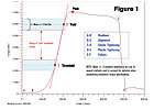
Figure 1 depicts a typical torque vs. angle of rotation trace for a normal hard joint where the fastener threads into a tapped hole or free-running nut. This is often referred to as a “torque-angle to failure” trace. The segment of greatest interest, C-D, is defined as the endpoints of a straight line aligned to the trace. That the trace follows a straight line indicates that the increase in resistance for a given angle of turn is constant. In other words, the joint is behaving in an elastic manner.
To meet our goal of maximizing clamp load, we need to make sure the maximum allowable installation torque does not exceed point D or fall below point C, allowing for statistical variation in each point. Note that point D is not always determined by the start of bolt yield, but rather by compressive yield of the joint members.
The most common cause is high stress under the bolt head or nut due to the small area. An indication of this is when the ratio of yield to peak torque is much less than the ratio of the bolt’s yield to tensile strength. It is not important that the element determining point D is known when the yield of any joint component during tightening is not desirable, as is usually the case.
While the ability to interpret the torque-angle trace is required, so is knowledge of how to generate it. The most basic hardware needs are a torque transducer and a data acquisition device that can graph the output of the torque sensor continuously during tightening.
Unless it can be assured that the bolt is being turned a constant speed throughout the test with a constant speed motor, the torque sensor will also need to provide angle measurement so the trace’s slope will not be influenced by variation in the speed of rotation. Two options are a socket transducer installed in-line between socket and wrench or motor, or a digital torque wrench with graphing and angle measurement capability. A
Therefore, for a given diameter (D) and grade of fastener, assumptions need to be made as to the torque-tension coefficient (K), and the force generated by that bolt tension (F). These assumptions are usually stated in tables, and are commonly K=0.2 and F = 75 percent of proof load (the minimum load resulting in bolt yield).
So, unless a K factor specific to the actual material and finish is used, a single torque value is judged universal for all applications of a given fastener size and grade. This is, of course, too simplistic when the cost of joint failure is high and market demands require highly reliable and efficient designs. However, most bolted joints enter production with installation torque based on these textbook estimates.
The objective of this column is to provide engineers with a path to improved torque selection within a reasonable budget and allocation of resources. Let’s first identify the primary limitation of the reference table. While T=KDF ignores a number of issues, the largest error results from not having accurate values for the torque-tension coefficient K.
We can avoid using this unpredictable value if we don’t need to estimate bolt tension. Because bolt tension (rather than torque) is the quantity that determines the performance of a given joint, this might appear foolish. However, the objective is to achieve better results than with use of reference tables, and the approach described here can accomplish this by measuring torque only. It is based on the assumption that one wants to achieve the greatest clamp load that wouldn’t cause the clamped components or the fastener to yield.
Figure 1 depicts a typical torque vs. angle of rotation trace for a normal hard joint where the fastener threads into a tapped hole or free-running nut. This is often referred to as a “torque-angle to failure” trace. The segment of greatest interest, C-D, is defined as the endpoints of a straight line aligned to the trace. That the trace follows a straight line indicates that the increase in resistance for a given angle of turn is constant. In other words, the joint is behaving in an elastic manner.
To meet our goal of maximizing clamp load, we need to make sure the maximum allowable installation torque does not exceed point D or fall below point C, allowing for statistical variation in each point. Note that point D is not always determined by the start of bolt yield, but rather by compressive yield of the joint members.
The most common cause is high stress under the bolt head or nut due to the small area. An indication of this is when the ratio of yield to peak torque is much less than the ratio of the bolt’s yield to tensile strength. It is not important that the element determining point D is known when the yield of any joint component during tightening is not desirable, as is usually the case.
While the ability to interpret the torque-angle trace is required, so is knowledge of how to generate it. The most basic hardware needs are a torque transducer and a data acquisition device that can graph the output of the torque sensor continuously during tightening.
Unless it can be assured that the bolt is being turned a constant speed throughout the test with a constant speed motor, the torque sensor will also need to provide angle measurement so the trace’s slope will not be influenced by variation in the speed of rotation. Two options are a socket transducer installed in-line between socket and wrench or motor, or a digital torque wrench with graphing and angle measurement capability. A
Looking for a reprint of this article?
From high-res PDFs to custom plaques, order your copy today!


