Press-Fit Connectors Attach Without Solder
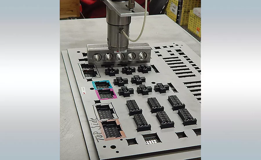
Würth Elektronik ICS Inc. relies on several toggle and pneumatic presses to press-fit pins and connectors into PCBs of all sizes and shapes. Photo courtesy Würth Elektronik ICS Inc.
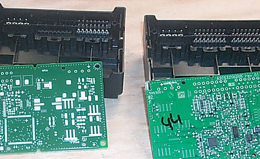
An automotive Tier 1 uses press-fit technology to assemble and test two types of PCB housings. One features a molded-in 16-pin connector; the other has two 16-pin connectors. Photo courtesy Schmidt Technology Corp.
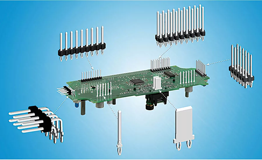
Made of copper alloy, press-fit pins come in different thicknesses and widths. Photo courtesy Autosplice Inc.
Positronic manufactures power and signal connectors for a variety of industries.
Photo courtesy Positronic
A common misconception about manufacturing (especially among the general public) is that it’s void of innovation. The fact is, new assembly technologies are constantly being developed and introduced to the marketplace. Sometimes, however, an innovation must be modified to become mainstream.
Such is the case for printed circuit board (PCB) assembly. From the early 1940s to the early 1990s, nearly all PCB components were attached with one of three methods: point-to-point soldering, wave soldering or reflow soldering.
Few components were assembled using press-fit technology. Developed by the telecom industry in the late 1970s, this solderless method involves pressing copper-alloy pins (separately or premolded into plastic connectors) into through-holes to form a gastight, electromechanical connection.
The method drew little interest from other industries because the solid press-fit pins initially used deformed the through-holes and caused microcracking in boards. That changed in the late 1990s with the development of compliant press-fit pins, plating of through-holes and the introduction of servo-electric presses offering precise control over the insertion process.
“Automotive suppliers of instrument clusters and noncritical switch assemblies first started using press-fit technology more than 10 years ago,” notes Joe Lynch, director of Interplex Industries Inc. As these suppliers became more comfortable with its reliability, they later deployed press-fit for more critical functions like airbag sensors and crash-detection control systems. Now the method is mainstream because it also offers repeatability and easy assembly.”
For the past few years, an automotive Tier 1 has used press-fit technology to assemble and test two types of PCB housings. One housing features a molded-in 16-pin connector with four power pins. The other housing has two 16-pin connectors and four power pins.
Assembly and testing is done in a semiautomatic workstation made by Schmidt Technology Corp. A worker places either housing (with PCB on top) onto a slide table, which transfers the housing to a nesting fixture. The PCB is positioned so the connector’s pins are properly aligned with the through-holes.
Looking for quick answers on assembly and manufacturing topics? Try Ask ASM, our new smart AI search tool. Ask ASM
Upon cycle initiation, a camera takes a picture of the housing and PCB, and a scanner reads the PCB’s bar code. If the components are not compatible, a “not OK” message appears on an HMI and the fixture returns the housing to the slide table. If the components are compatible, the housing is uploaded to a 420 ServoPress and its ram presses the PCB onto the pins in 1.5 seconds.
After assembly, the camera performs pin height inspection to verify accuracy to within 0.003 inch. The completed housing is then transferred to an unload location. Total cycle time is 12 seconds. Bar code scanning enables complete product traceability.
“According to the IEC1709 norm, press-fit connections are at least 10 times more reliable than soldered connections,” claims Glenn Nausley, president of Promess Inc. “By using press-fit instead of solder, manufacturers eliminate thermal stress on the board, heat development on sensitive components, cold solder joints and shorts caused by solder bridging.”
Much Better Than Soldering
Press-fit technology offers many other advantages over pin-through-paste and selective soldering. For starters, solder is now lead-free and must be reflowed at high temperatures, which can damage the connectors and board.
Press-fit assembly can be easily automated, whereas secondary soldering processes are often done manually and are slow, expensive and lacking in quality control. Also eliminated are all fumes, gases or cleaning fluids needed for soldering that often reduce contact reliability.
Lynch points out that compliant press-fit pins provide a direct contact interconnect without any metal filler or voids in the connection. The pins’ compliance also provides some beneficial flexibility, including slight movement to compensate for high vibration and thermal cycling environments.
A Couple Components
Press-fit pins are made of copper alloy, and each pin carries three to 50 amps. Originally, the pins were solid with a rectangular cross-section that deformed the through-hole during insertion. To combat the problem, suppliers developed compliant pins that are several thousandths of an inch greater than the diameter of the PCB hole but compress during insertion.
Once inserted, the pin expands and presses against the rigid sides of the hole to form a gastight joint. In addition, the joint’s high local pressure produces a cold weld effect that provides mechanical and electrical integrity.
The most popular compliant pin design is the “eye of the needle,” which features flexible beams on each side. Other compliant designs are the C-section and action pin. C-section pins are crescent-shaped and tapered so they expand or contract to contact the circumference of the through-hole. Action pins feature a split-beam design.
Besides preventing damage to the PCB, compliant pins provide spring force for retention and permit connector repairs. They also require lower insertion force than solid pins and allow multiple press-in cycles. Because of these benefits, compliant pins are generally preferred.
In certain high-temperature (above 125 C) applications, press-fit pins need to be plated for added durability. A tin-immersion or electroless-nickel plating is usually sufficient. However, the tin should be kept as thin as possible (1 micron) so it doesn’t scrape off when the pins are inserted.
“The most popular pin thicknesses are 0.64 and 0.81 millimeter, to fit into 1.016- and 1.486-millimeter holes, respectively” explains Lynch. “Factors that determine proper thickness include the pitch or density of pins within a connector, and pin-strength and current-carrying requirements. For example, applications that emphasize high mechanical strength or power, such as hybrid cars, require our Macro pins (1 and 1.2 millimeters thick). But, parts that need PCBs to quickly transfer data, are better off with our Micro or Mini pins (0.2 to 0.4 millimeter thick).”
Micro pins are specifically designed to meet the requirements of micro wearable technology, including smart watches, wristband monitors and connected glasses. Micro and mini pins integrate easily with sensors, LEDs and other specialized modules used in mobile medical monitoring devices. The Macro series is for industrial bus bars and other high-current products with large heat sinks, multiple internal substrates and complex control circuitry.
Autosplice Inc.’s press-fit pins come in two thicknesses (0.64 and 0.81 millimeter) and eight widths (0.64, 1, 1.5, 1.8, 2.8, 6, 6.3 and 9.5 millimeters), according to Frederick W. Grabau, VP—global business development for Autosplice. Insertion and retention forces for the 0.64-millimeter pin are 59.6 and 46.7 newtons. For the 0.81 pin, they are 132.1 and 88.1 newtons.
Operating temperature for all pins is -40 to 125 C, and they can withstand 125 C for 1,008 hours. Right-angle pins (single and double row) are also available for joining perpendicular PCBs. All products are offered with RoHS lead-free plating.
Connectors are molded of durable plastic with a wide range of pins. They may contain as few as three pins, and as many as 256 pins.
The trend is for them to increase in density and have more stringent requirements when used in harsh-environment applications. As data-transfer speed requirements increase, the differential signal, power and electrostatic discharge grounding will need to be more tightly incorporated into the connector.
Lynch says Interplex recently developed a unique connector for an automotive supplier. The connector is 1.2 inches wide and features 120 pins that are each bent 90 degrees and 1.6-inch long.
Insertion and Inspection
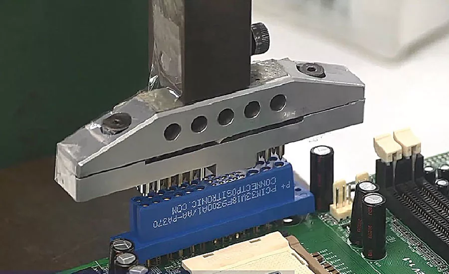
Pressing a connector into a PCB is a simple process that can be manual, semiautomatic or fully automatic. After the PCB is fixtured and the connector positioned and aligned on top of it (or vice versa), the press is activated. Any type of press (toggle, hydraulic, pneumatic and servo-electric) may be used, so long as it has the proper tooling and its ram imparts the required force.
Pin insertion (one or many) is also simple and may be manual, semiautomatic or fully automatic. Manual and semiautomatic insertion requires the pins to be positioned in the proper holes and secured with a support piece (usually made of UHMW polyethylene) that won’t damage the PCB. Pins may also be placed into spring-loaded upper tooling that releases them during insertion.
Fully automatic insertion is done with a stitching-type machine, such as the LZ-Insert-2M made by Lazpiur, that presses each pin into a through-hole at a high volume (up to six per second). A measuring device below the PCB verifies proper insertion force for each pin and ensures that it protrudes slightly out of the through-hole bottom. Proper board design allows clearance for the protrusions so performance isn’t affected.
At its Dayton, OH, plant, Würth Elektronik ICS Inc. relies on several toggle and pneumatic presses from BalTec Corp. to insert press-fit pins and connectors. Workers there use presses with forces up to 56 kilonewtons to assemble PCBs of all sizes and shapes for agricultural equipment, fire trucks, golf carts and motor coaches.
Chuck Rupprecht, vice president and general manager for BalTec, says the company’s VK and L-VK series are frequently used for low-volume PCB assembly. The toggle presses offer force capacities from 5 to 12 kilonewtons. They also feature a square ram to prevent rotation.
Connector suppliers often specify upper and lower tooling for each of their pin types or connectors. Most connectors, including right-angle models, can be inserted with flat-surface upper tooling. The lower tooling supports the PCB during pressing.
Some suppliers make connectors with holes at the top that expose the pin tops. Tooling protrusions fit into these top holes to lock with the connector and ensure that equal insertion force is applied to each pin during pressing.
To prevent board deformation, a distance of 0.5 to 1 millimeter should be maintained between the PCB and connector bottom during pressing. The connector’s plastic housing must also be strong enough to support the press force.
“Always make sure the press can provide enough force for the application,” recommends Rupprecht. “Let’s say that each pin might only need a few pounds of insertion force. But, if there are more than 100 pins in a connector, it probably needs about 500 pounds of force. And if the application calls for multiple connectors to be inserted simultaneously, you might need a press with 1,000 or 2,000 pounds of force.”
Equally important, according to Nausley, is making sure there is proper initial engagement between the connector and PCB. Otherwise,, a good insertion is impossible.
“Many things can prevent proper engagement, including a slightly bent pin, using the wrong connector, imperfectly formed holes and a machine malfunction that causes improper alignment,” says Nausley. “When improper engagement occurs, the press usually damages the connector and board to the point that they’re unusable.”
To prevent this problem, Promess developed the Digital Signal Conditioner (DSC) for its electromechanical press. The DSC has a built-in linearization algorithm that accurately measures initial engagement force.
Nausley says the algorithm, in conjunction with closed-loop positioning control, ensures that the press stops mid-cycle if it detects a problem.
Most board manufacturers also rely on some type of press-fit process monitoring to ensure quality assembly. Simple load cells can be connected to a manual press to measure and record insertion force. Semi- and fully automatic equipment are able to document several variables for the board and connector, and display them as a force-distance graph.
“Secondary inspection is needed beyond press-force monitoring,” claims Dave Zabrosky, sales manager forSchmidt. “This inspection can be initiated by a simple pogo switch integrated into upper or lower tooling.”
Zabrosky says the ServoPress and ElectricPress series are programmable and capable of verifying pin presence before and after pressing, the height of all pins relative to each other, PCB levelness and board elevation relative to PCB housing.
Looking for a reprint of this article?
From high-res PDFs to custom plaques, order your copy today!


