advertisement
How To Select and Install M85049/128 Shield Termination Bands Onto Wire Harnesses

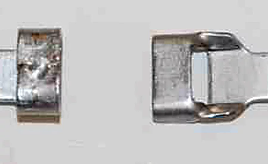

M85049/128 Shield Termination Bands are available in two distinct configurations, Stamped and Welded Buckles, and two different widths, .250 in. (6.350 mm) and .125 in. (3.175 mm). The bands come flat or pre-coiled and ready for use. The buckle for the M85049/128-3, M85049/128-4,
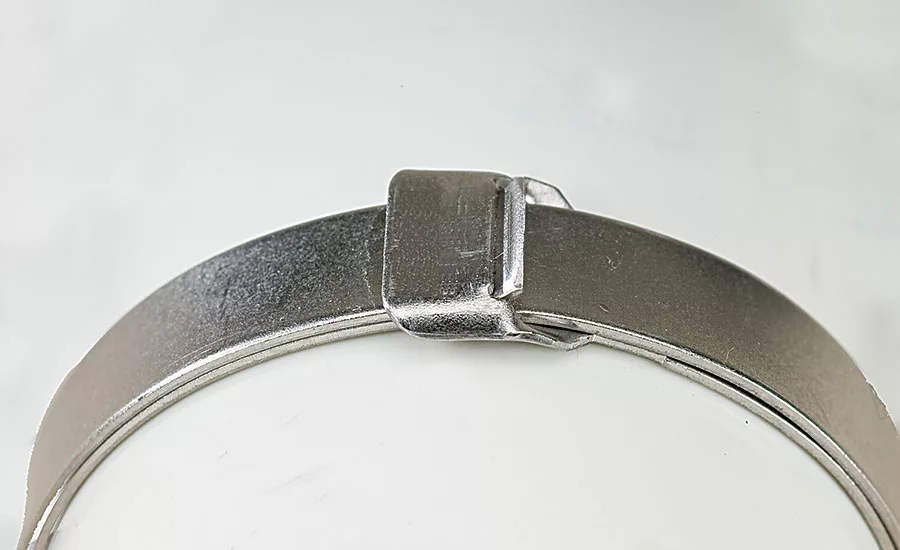
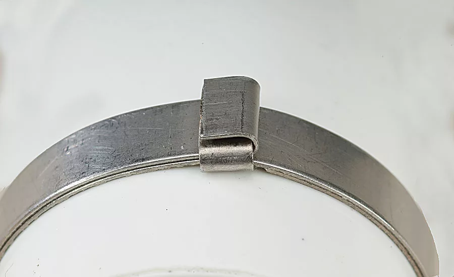
M85049/128-7, and M85049/128-8 bands is a STAMPED buckle. This configuration is low-profile style with a slot for the other end of the band to pass through. The buckle for the M85049/128-1, M85049/128-2, M85049/128-5, and M85049/128-6 bands is a WELDED buckle. This configuration is folded style with a loop for the other end of the band to pass through.
One Step Installation
Bend & Cut Flush (No Fold-over)
Two Step Installation
Fold-over Tab
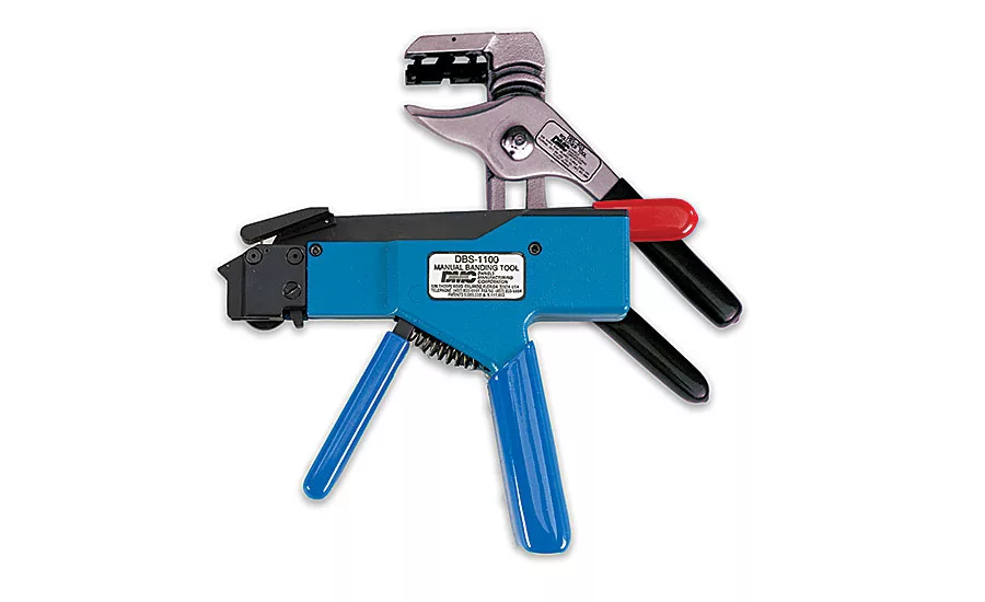
SAE AS81306 Specification was established to standardize shield termination tools.
ONE STEP TOOL FOR
M85049/128-3, M85049/128-4, M85049/128-7, and M85049/128-8 Stamped Buckle Bands
TWO STEP TOOLS FOR
M85049/128-1, M85049/128-2, M85049/128-5, and M85049/128-6 Welded Buckle Bands
CALIBRATION VERIFICATION equipment is available from DMC and recommended to be used periodically to assure correct tensioning of the bands (consult user instructions for details).
EMI/RFI BAND APPLICATION SYSTEM
FOR .125 & .250 SHIELD TERMINATION BANDS
Looking for quick answers on assembly and manufacturing topics? Try Ask ASM, our new smart AI search tool. Ask ASM
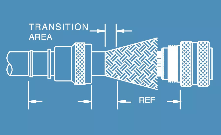
Careful measurement should be made prior to installing the backshell. The outer jacket is then uniformly removed at a distance which would allow the braid to make a comfortable transition onto the backshell termination area. This dimension will vary depending upon the differences between cable and backshell diameters or other application dependent factors.
The braid is then trimmed to a length which will allow it to extend 1 inch past the backshell termination platform. Then the braid is carefully folded rearward to expose the wires which will be inside the backshell.
A sufficient number of wraps of self-vulcanizing tape (normally red in color) are applied over the wires to build up a diameter slightly less than the inside diameter of the backshell. Care should be taken not to apply tension to the contacts located in the outer perimeter of the connector.
These layers of tape are followed by a minimum of one layer of Teflon tape which will prevent adhesion with the backshell and other components.
The backshell is then installed onto the connector, using a nonabrasive tool such as a strap wrench. The braid is then carefully moved from under the backshell. It is important to retain the woven characteristics of the braid during this step.
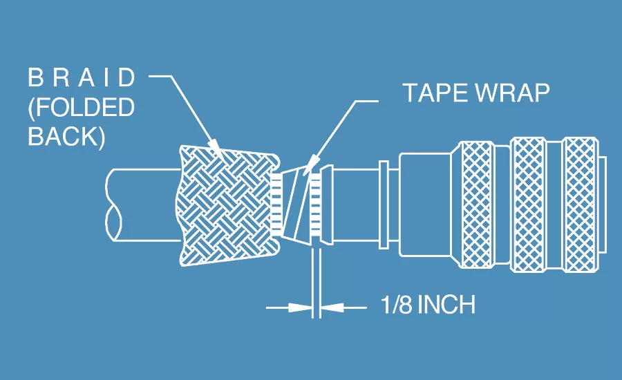
Use self-vulcanizing tape or a preformed component to build up the area behind the backshell. It is important that the braid is sup-ported in the transition from the backshell rear diameter to the natural diameter of the wire bundle. Leave approximately 1/8 inch spacing between the tape wrap and the backshell.
The braid is pushed into position over the backshell -termination platform. Care must be taken to make sure the weave is uniform and no large “windows” are present.
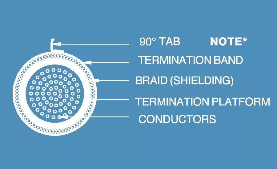
A shield termination band is then loaded into the tool. The band is then slid over the connector/backshell assembly into a position of -alignment with the -ter-mination platform. Apply an adequate amount of pressure in line with the cable as it enters the backshell to allow the 1/8 inch space to be reduced to zero. The tool is then activated to the preset tension. The band is then bent sharply at the buckle approximately 90° then cut-off using the cut-off lever on the tool (applies to two-step only). If the band is uncurled for any reason, it must be double looped through the buckle before termination.
The 90° tab is then curled and folded back over the buckle using the rollover tool (applies to two-step only).
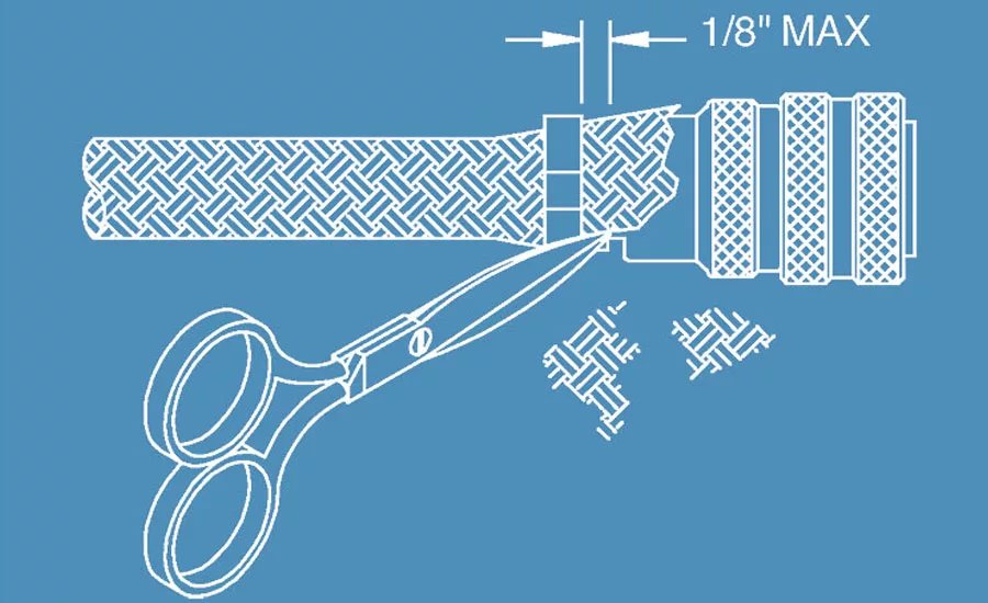
For braiding a non-jacket cable use fine point shears to trim the excess braid as close to the connector side of the bands as possible. Do not leave any unsecured braid wires longer than 1/8 inch. Do not allow the trimmed wires to fall in any areas where they may present a foreign object damage hazard.
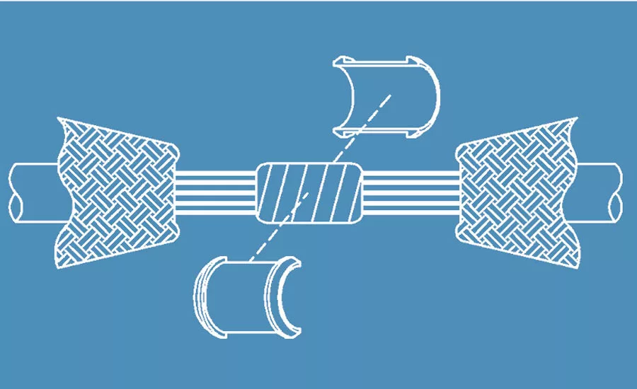
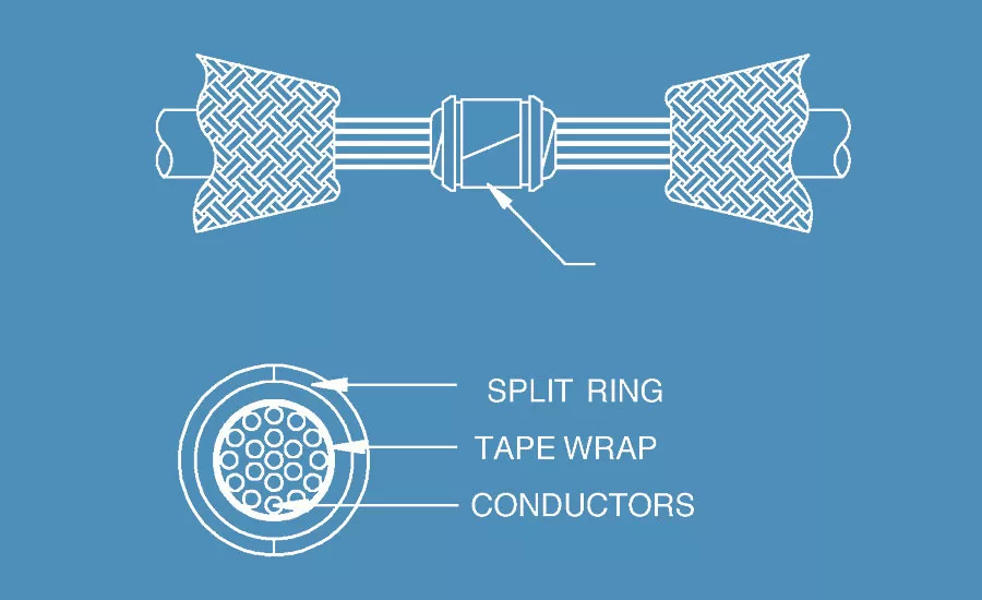
Procedure for Splicing
The jacket is present, and shield has been cut and separated to expose the wires requiring service. Care must be taken to avoid damaging the insulation on internal wires. The required service is then completed.
The wire bundle is then protected by a few wraps of self-vulcanizing tape followed by 2–3 layers of teflon tape. An appro-priate size split-ring set is then selected and installed. One layer of teflon tape is applied over the split ring set to hold the halves in position while the next steps are being performed.
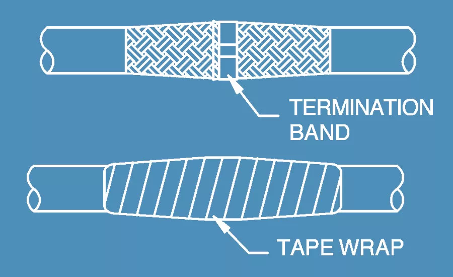
The braid is then overlapped across the split ring set. Be sure the braid ends protrude completely under the band in both directions. Heat-shrinkable tape is then applied over the splice. When a jacketed cable is used, be sure the tape extends onto the jacket in both directions.
Looking for a reprint of this article?
From high-res PDFs to custom plaques, order your copy today!


