Connector, Cables, and Antenna Selections for IoT Modules
The choice of cable, connector, or antenna relies heavily upon the application.
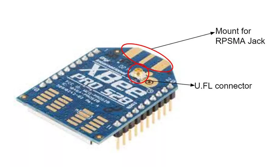
Figure 1: Standard XBee module with U.FL connector and mount for RPSMA connector.

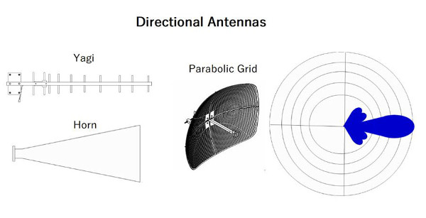
Figure 2: Basic illustration of directional and omni-directional antennas and approximate associated gains with commonly used antennas.
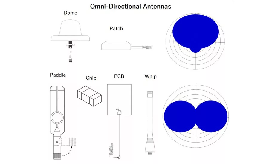
Figure 3: Illustration of a basic radiation pattern for specific omni-directional and directional antennas commonly used in Wi-Fi, LAN/WAN, Bluetooth, GPS, ZigBee, and Z-wave applications.
In an increasingly connected world with the introduction of machine-to-machine (M2M) communications, technologies such as Bluetooth, ZigBee, Z-wave, and Wi-Fi have opened up wireless prototyping opportunities not only for major corporations but small businesses and hobbyists. According to Grand View Research, the global IoT market size was valued at $605.69 billion three years ago, serving the consumer, manufacturing, retail, transportation, and healthcare industries. From smart Bluetooth trackers to Bluetooth and Wi-Fi enabled smart door locks and home automation, M2M communications are quickly forming the foundation for a host of ‘smart’ applications.
Readily accessible System-on-chip (SoC) development boards and prototyping kits with Wi-Fi, Cellular (3G/GSM), GPS, Bluetooth, ZigBee, and Z-wave connectivity along with deployment platforms such as raspberry pi offer to break down the barriers in generating homebrewed technology solutions. While the open-source software development community allows for leaps in advancements of software platforms, practical information in implementing the RF components can often be difficult to access. The connectors, cables, adapters, and antenna selections and how to arrange them are amongst some of the custom choices made in generating good transmission/reception of a signal.
Connectors: Does it make a difference what connectors I use?
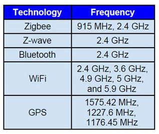
The type of connector used really depends on the size and frequency range of the application. As shown in Figure 1, small XBee boards will often have a U.FL connector or a mount for an RPSMA for mating with larger antennas. Generally, the commonly used ISM bands (shown in Table 1) do not go above 6 GHz so that eliminates many options for connectors. Wi-Fi access points and accessories will commonly use RPSMA, RPTNC, MC-Card, MCX, and MMCX connectors. N-type, 4.3-10, and DIN connectors will often be used with higher gain transmit antennas in distributed antenna systems (DAS) and base stations as these connectors have a higher power handling (and less associated passive intermodulation distortion (PIM)) than the connectors widely used in the ISM bands for commercial/consumer applications.
U.FL
The U.FL connector is known by several names in the industry including IPX, IPEX, UMCC, AMC, MH, and are often the default choice of connector on IoT modules. Their dimensions are ideal for small form factors and the ‘push-on’ mating style eliminates the need for any torque wrenches. These connectors can perform up to 6 GHz (convenient in 5.9 GHz Wi-Fi applications) and have several antenna options to choose from: wire antenna, chip antenna, or a pigtail (or an adapter/thin wire to another type of RF connector) in order to mate to an externally mounted antenna. Antennas are normally mounted external to an enclosure if the enclosure casing is metallic as this will greatly impede the signal.
RPSMA
RPSMA, or reverse polarity SMA, was originally introduced in the late 1990s as an uncommon connector in order to prevent consumers from mating their Wi-Fi devices to amplifiers and external high-gain antennas causing RF interference on an already enormously congested spectrum. Today, the RPSMA connector is no longer uncommon and adapters can be readily found and purchased as a commercial off-the-shelf (COTS) part. RP-SMA connectors can often be found attached to rubber duck antennas on peripheral component interconnect (PCI) wireless cards found in desktop computers or on GPS receivers, transceivers, and handheld mobile radios. Since its inception, the RPSMA connector head has mostly proliferated in Wi-Fi, ZigBee, or Z-wave antenna applications in the popular ISM bands. Contrary to the RPSMA, the SMA is a more broadly used connector in the entire RF space including test/measurement, radar, electronic warfare, and wireless and telecommunications applications.
Which Antenna Should I Choose?
The choice of antenna also heavily depends upon the application since factors such as power needed (depending upon link distance and obstructions), directionality, polarization, and gain will vary.
Gain, Directivity & Polarization
As implied by the name, directivity is a measurement of the concentration of a beam radiated from an antenna, as depicted in Figure 2, a highly directional antenna will have a significantly higher directivity than an omni-directional antenna. An isotropic antenna, or an antenna that radiates equally in all directions has zero directivity. Gain is a measurement of the total power radiated from an antenna and is often discussed as a function of angle in a three-dimensional space (gain pattern). It differs from directivity in that it accounts for the losses from the antenna, or the antenna’s efficiency (E) as shown in the Equation 1: Gain = E*Directivity. [1]
Looking for quick answers on assembly and manufacturing topics? Try Ask ASM, our new smart AI search tool. Ask ASM
Since gain is a more practical parameter, it is often specified on datasheets in units of dBi, or the power relative to an isotropic antenna in the peak direction. Gain is a relative term as more power inputted into the antenna may allow a signal to travel further but a higher gain will allow for an increase in the strength and clarity of a signal. System parameters such as power handling of the transmitter, distance for travel, sensitivity of the receiver, and potential signal obstacles should all be weighed in the selection of an antenna (aka link budget analysis).
Since an antenna essentially channels electrical power into electromagnetic radiation, or oscillating electric (E-field) and magnetic fields (H-field), it is important to understand the antenna polarization, or the orientation of the ‘radio’ wave. This orientation is normally determined by the E-field and can be linearly (horizontal or vertical), circularly, or elliptically polarized. A linearly polarized antenna has the E-fields and H-fields traveling in a singular direction (plane wave) with no field variation in the two orthogonal directions. Circularly polarized antennas emit EM waves in the orthogonal direction, or 90˚ out of phase, while elliptically polarization emits two plane waves with a relative phase other than 90˚.
Antennas that are often used in IoT modules such as whip, rubber duck, PCB, and chip are all linearly polarized. The fact that the antenna installed is horizontally or vertically polarized is of no consequence, so long as the transmitting and receiving antennas are polarized in the same direction. For instance, the transmitting omni-directional rubber duck antennas normally used in Wi-Fi access points are often vertically polarized and the receiving antennas built into the sides of laptops become vertically polarized when the monitor is in the upright position [2].
Chip vs. PCB vs. Wire Antenna
Typically, IoT modules that leverage a mesh topology such as Zigbee, Z-wave, and more recently Bluetooth SIG do not need an externally mounted antenna as lower gain chip or PCB antennas will do the job—the mesh topology relies on multiple coordinated nodes to transmit data over an extended range. In cases where there is a large antenna, there is either a pigtail from the U.FL connector on board or a direct mating between an RPSMA plug on the module to a right-angle RPSMA jack connected to the antenna. Wire antennas will mate directly onto the dongle via a U.FL connector and are fairly uniform omni-directionally (donut shape) and so is not as sensitive to orientation as PCB and chip antennas. Ceramic chip antennas tend to be smaller than PCB antennas where PCB antennas are much more cost-effective. Often chip antennas have a cardioid (heart-shaped) radiation pattern and are attenuated in certain directions [5]. PCB antennas are composed of an array of conductive traces and generally have a higher gain than ceramic chip antennas (as noted in Figure 2). Where size and weight are a major concern such as in wearable devices, chip antennas are generally used.
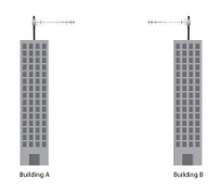
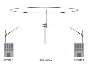
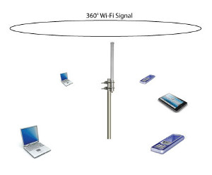
Figure 4: There are a wide array of antennas that can be used in IoT deployments depending upon the type of connectivity used.
Whip and Rubber Duck Antennas
When leveraging networks with point-to-multipoint communications such as the Wi-Fi star topology, usually a higher gain antenna is necessary. In these cases omni-directional rubber duck antennas and whip antennas are normally employed. These antennas are typically directly mounted to the PCB through a coaxial plug (SMA, RPSMA, etc). In mobile RV and marine applications where a high gain and wide coverage over a horizontal plane is necessary, there are whip antennas that can go up to or beyond 7 dBi. Still, the higher the gain of a whip antenna, the flatter the radiation spread will be.
Patch Antenna
From real-time pet, child, and bike tracking to logging hiking trails, there are a plethora of custom modules that use GPS connectivity. The patch antenna configuration is normally used in GPS modules as it is small (as shown in Figure 3); the antenna radiation pattern is omni-directional with nearly hemispherical coverage (~160˚), and either right-hand or left-hand circularly polarized (RHCP/LHCP) enabling reception of satellite signals in any azimuthal direction, and from zenith to horizon [3]. Often, satellites will employ circularly polarized antennas so circularly polarized receiving antenna is most viable for proper reception. For GPS modules with long cables leading to the antenna, active GPS patch antennas are used as they employ low noise amplifiers (LNAs) to enhance the sensitivity of the receiver—this mitigates the attenuation caused by the cable. The RG-174 cable is frequently used along with SMA, FME, MCX, or MMCX connectors and require a pigtail in order to mate with the U.FL connector on many IoT dongles. An additional factor to take into account when selecting an antenna is the bandwidth as the receiver’s antenna bandwidth is directly correlated to the accuracy—more frequency content of the satellite signal can then be processed [4].
Directional (Yagi, Parabolic Grid, Panel)
Point-to-point applications such as remote telemetry usually involve a long range and therefore require high gain antennas with high transmit powers. Yagi, parabolic grid (or dish), and panel antennas can be used for a highly directional beam to achieve vast link distances. Small Wi-Fi yagi antennas can also be mounted on a gimbal, servo motors, or rotated manually for long-ranged wireless sensing in unmanned aerial vehicle (UAV) applications [6].
Coaxial Feeds
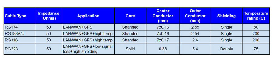
Higher gain and directional antennas (often for point-to-point applications) such as yagi, parabolic dish, and panel antennas or even high gain omni-directional antennas for point-to-multipoint applications (shown in Figure 4) will typically need to be mounted a distance away from the transmitting module. These applications will often leverage coaxial feeds with RG174, RG188, RG316, and RG223 cables.
These standard cables are all 50 ohms for impedance matching (reducing reflections and losses due to discontinuity). While the RG174 cable is generally most cost-effective and therefore most often used as a coaxial antenna feed, the RG188 and RG316 are rated for temperature extremes (up to 200C), as shown in Table 2. The RG172, RG188, and RG316 all have a stranded core for increased flexibility and tighter bend radius (useful for any tight installations). The high temperature rating can be beneficial in outdoor environments since heat from UV and other elements can quickly shorten the lifecycle of a coaxial cable as the cable jacket can swell, melt, or otherwise deform. The RG223 cable can serve the same applications but is designed with superb electrical performance as it has a lower attenuation with a solid inner conductor and protection from electromagnetic interference (EMI) with two layers of shielding.
It should be noted that there are low loss alternatives that generally outperform RG cables in virtually every aspect. These cables usually have a solid core with an additional layer of foil shielding for low attenuation and 100% coverage. The mechanical reliability of these cables are generally higher as they often employ strain reliefs on the connector-to-cable joint and also typically have well-performing cable jacket materials (resistance to: oil, chemical, UV, abrasion, etc).
The choice of cable, connector, or antenna relies heavily upon the application. Factors such as directivity, gain, and polarization can be taken into account for antenna selection while price, size, and frequency range are taken into account in choosing a connector. There are a plethora of coaxial cables with different cross-sectional areas which can be hard to sort through, still, there are some commonly used cables that essentially narrowed down by three necessities in commercial appliances: 50 ohm impedance, flexibility (and hence reliability), and cost.
References
[1]Earle, Aaron E. Wireless security handbook. Boca Raton, FL, Auerbach, 2006.
[2]Coleman, David D., and David A. Westcott. CWNA certified wireless network administrator study guide. Indianapolis, IN, Wiley, 2009.
[3]http://www.navipedia.net/index.php/Antennas
[4]Kaplan, Elliott D., and C. Hegarty. Understanding GPS: principles and applications. Norwood, Artech House, 2006.
[5]Faludi, Robert. Building wireless sensor networks. Beijing, OReilly, 2011.
Looking for a reprint of this article?
From high-res PDFs to custom plaques, order your copy today!


