IAM 2013
Think Inside the Box: Design for Manufacturing and Assembly
DFMA and the concept of reducing total part count will naturally spread across the organization saving time, money, materials and headaches.
An important part of being an engineer is the ability to design products such that they can be manufactured economically with existing technologies in an environmentally conscious way.
Many engineers are probably familiar with the terms DFM (Design for Manufacturing) or Design for Assembly (DFA).
DFA is a technique to minimize the total cost of the product by reducing total part count, assembly time and the complexity of the assembly process. DFM is a technique to minimize part cost though choosing the best manufacturing process, the optimal material and the best tool for making the product.
One of the recent trends in the design world has been to combine these two techniques (DFM and DFA) to design for both ease of manufacturing and for ease of assembly. The resulting concept, called Design for Manufacturing and Assembly, or DFMA, is increasingly becoming the method by which products are designed.
DFMA can be used throughout the entire product development lifecycle from concept selection to design tracking, cost estimating and product benchmarking. As an example, a cash register OEM redesigned one of their main products using the DMFA technique and was able to obtain an 85 percent part count reduction, a 75 percent reduction in assembly time, a 44 percent reduction in labor cost, 65 percent fewer suppliers, reduce the need for all assembly tooling and fasteners, save $1.1 million in product lifetime labor and free up 33 percent of the floor space dedicated to manufacturing.
Whole Product Analysis
Design for Manufacturing and Assembly (DFMA) focuses on the analysis of whole products as well as their constituent parts and subassemblies. If a significant portion of a product’s final cost comes from materials, it is reasonable to assume that the fastest way to reduce cost would be to eliminate parts/subassemblies. Boothroyd and Dewhurst, the pioneers in the DFMA process, developed the concept of theoretical minimum part count, which serves as a goal for the product designer to achieve, yielding a design with the fewest part/subassemblies possible.
To determine if a part is a candidate for elimination, a simple set of questions must be answered. One must ask if the part is required to meet the function of the design; if the part is required to move relative to other parts; if the part must be made of a different material than the other parts; and if the part is necessary for the service or disassembly of the product. If you can answer “yes” to any of these questions in regards to the part in question, then the part may be required. If the answer to all of these questions is “no” then the part is a good candidate for elimination. The exercise of how to design the product to hit the theoretical minimum part count is left to the imagination and creativity of the design team.
Looking for quick answers on assembly and manufacturing topics? Try Ask ASM, our new smart AI search tool. Ask ASM
Reducing the part count is a key benefit of utilizing DFMA.
Part count touches every department in an organization from engineering to sourcing, manufacturing, purchasing and sales to marketing, quality and customer service. Reducing the total part count has the obvious benefit of fewer SKUs to track and fewer raw materials used; but it has several hidden benefits as well. Reduced part count leads to fewer drawings to keep straight, fewer tolerance issues, fewer assembly stations/equipment (and thus less assembly labor required), fewer tools, jigs, fixtures, etc., necessary and a simpler supply chain overall.
Identifying Parts for Elimination
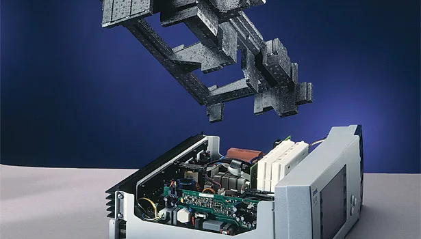
Typical candidates for elimination include any of the brackets, fasteners and sheet metal trays whose only purpose is to hold together all the parts and subassemblies that need to be interconnected so that the product will function. As such, these parts are the ones most often highlighted for elimination when the theoretical minimum part count questions are asked. One way to reduce the total number of screws, fasteners, etc., is to employ a different method to house the internal components such as by using an internal chassis made from expanded polypropylene (EPP) foam.
The resiliency of the EPP foam allows internal components such as printed circuit boards, fans and power supplies to be held in place using a friction fit; no other attachments are necessary. The components are simply slid or snapped into place and then held in place by the foam. As a result, any of the screws, fasteners and brackets that do nothing more than hold the components in place can be eliminated, right in line with the principles of DFMA.
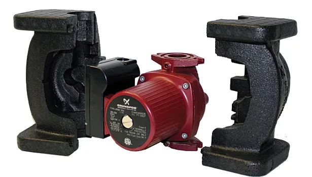
One method of replacing the internal structure of a device with EPP is to use a sandwich approach with top and bottom EPP pieces that lock the components between them. Instead of attaching a muffin fan or circuit board to a wall or chassis with screws, EPP can be used such that the components are snapped into place in the bottom piece of foam, and then the top piece of foam is placed over the components in a “sandwich” fashion. This not only eliminates fasteners and brackets, but it can also help to dampen vibration and/or noise created by the fan.
Quicker Snap Fitting
During assembly, snap fitting various components into the foam is much quicker than taking the time to assemble using four screws (or more) to attach a component to the chassis. Using the foam sandwich method will result in a significant labor time savings – in some cases upwards of 50 percent labor savings has been achieved – as well as eliminate the need for additional assembly tools such as a screwdriver. Additionally, when a technician needs to go in to service the unit and replace or repair certain components, being able to remove and replace components quickly will make repairs much more efficient. Finally, with this snap fit feature, removing and separating components for disassembly and recycling at end of product life is much easier.
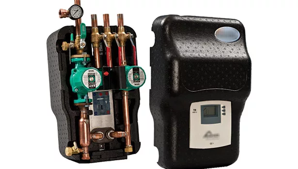
In addition to resiliency, the material properties of EPP are such that a foam chassis structure can be very strong and rigid. Because of this, the outer housing on a device can be made with a thinner gauge material, and, in some cases, be eliminated completely, leaving the foam as the internal protection, support and outer housing. In the case of the hot water heater application shown, the foam acts as the internal support and the external housing as well as protects the unit during shipment. In the case where the external housing must have a particular texture or surface finish, the foam can have a variety of textures molded into it in order to achieve the desired look on the finished product.
One unique benefit of EPP is the ability to mold different types of channels into the part. Channels are helpful for use in routing tubes, wires or even directing air flow. Small crush ribs, molded into the sides of the channels allow the wire or tubing to be snapped into place and held there without the need for any additional attachments. In the case of a channel for air flow, the channel can be designed and molded such that air is directed away from the components and out to the heat sink. By directing the airflow within the chassis to precisely where it is needed, smaller fans can be used which often results a quieter and more energy efficient design.
In one application, a medical device has an external heat sink with the foam on the inside directing airflow in all the right places; the outer housing of the device itself actually acts as a heat sink.
Shortening Design Process, Too
DFMA can shorten the design process by as much as 40 percent and though more time is spent upfront on the initial concept design phase, less time will be spent later in the project on design changes and documentation. Using EPP to create the inner chassis of a product can also reduce the design and prototyping time because prototypes can be made without the need for any special prototype tooling.
Once the initial design has been completed, a preliminary prototype can be produced using a CNC mill. The designer creates the design using a 3D CAD modeling program, and then programs the CNC machine to cut a billet of the EPP material. The prototype can be tested by assembling the components in place and, if modifications are necessarily, the engineer can use a razor knife to make the necessary adjustments. The improvements are then added to the CAD model and the next iteration of the prototype can quickly be made on the CNC mill.
An inner chassis made from EPP gives product designers more flexibility in their designs because they have more freedom in how the internal chassis is designed relative to the outer sheet metal or plastic housing. Designers no longer have to worry about how the components will attach to that structure, and only need to worry about designing the foam to fit into the outer housing and allow for other components to snap fit into place. In some cases, they may even be able to eliminate the outer housing all together. In the case where the outer housing can’t be replaced, designers are given the freedom to change the inside of the device without changing the outer housing.
A Touch of Creativity
EPP can be molded into extremely complex shapes and thus allows a lot of room for designer creativity. However, since the use of EPP foam as an internal component of appliances and devices is a relatively new concept in the United States, often the most difficult part is teaching designers to literally think about designing their products in a completely new way. That is where DFMA comes in.
Teaching a designer about DFMA and the concept of reducing total part count will help him or her to start thinking in new ways. This in turn can help think about reducing as many parts as possible and make the concept of using EPP as an inner chassis much more feasible. Designers can then take that knowledge and share it with fellow engineers to help expand the concept beyond their project team or work group.
Once the idea is planted, it will spread across the organization saving time, money, materials and headaches. Start thinking inside the box – by literally replacing the insides of said box with foam.
Click here to see more content from International Appliance Manufacturer.
Looking for a reprint of this article?
From high-res PDFs to custom plaques, order your copy today!


