Large, thick circuit boards pose considerable challenges for a lead-free assembly process.

With electronic devices getting smaller and smaller, it’s somehow comforting to know there are still printed circuit board assemblies bigger than the proverbial bread box.
It’s comforting, that is, unless you’re responsible for assembling a PCB more than 18 inches wide and 0.125 inch thick. That’s because large, thick circuit boards are challenging for every aspect of the assembly process, from printing to reflow. Even the simple task of transferring these boards from one machine to another requires specialized equipment. Indeed, most electronics assembly machines are designed for boards less than 14 inches wide.
“A tremendous amount of people are asking for machines that can handle boards 24 inches square or bigger,” says Scott Wischoffer, applications engineering manager for Fuji America Corp. (Vernon Hills, IL). “Generally, anything bigger than 18 inches square is considered a large board, but there’s a new level of large board out there now. These boards can have 25 to 40 layers; they can be as thick as 3/8 inch; and they can weigh 10 to 15 pounds without components. I’ve handled a board that was 25 by 36 inches, and they can get bigger than that.”
Such large PCBs are typically backplanes and motherboards for telecommunications, Internet, aerospace, defense and high-end server applications. These are high-mix, low-volume assemblies, and they are very expensive.

Printing and Placement
When applying solder paste to large PCBs, maintaining a level surface on which to print is a major challenge. Unusually wide boards tend to sag under their own weight. They can also exhibit warpage, particularly if the board is double-sided and has already gone through reflow once. Bottom-side board support is critical.Another concern is ensuring even coverage and squeegee pressure. The standard size for a framed stencil is 29 by 29 inches, though the actual print area might measure 22 by 22 inches, after allowing for the frame and binding material. Printing paste across a long, wide area can produce “serious lapses in printing accuracy, due to the longer travel distance along the arc line,” says Ed Stone, sales manager at Manncorp (Huntingdon Valley, PA). “There can be a dead spot in the center of the print area, and another dead spot at the edges. These spots do not come into play when printing smaller boards.”
A frameless stencil system will enable engineers to print to the edges of a 29 by 29 inch stencil. To print across an even larger area, special printers and custom frames are necessary.
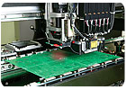
Maintaining a level surface is just as important to component placement as it is to printing. Here, too, bottom-side board support is important. In addition, some placement machines use a technique called terrain mapping to compensate for small variations in board height. Prior to placing components, the machine measures the height of the board at multiple locations. This data is used to create a topographical map of the board. Based on the map and the size of the component, the placement head adjusts its motion to ensure accurate positioning.
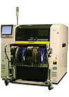
Depending on the size of the board, engineers may not need a special machine for component placement. The machine can simply populate the board in sections. If the placement head is unable to cover the entire board, a special machine is needed. In that case, engineers should look for a machine equipped with linear, rather than rotary, encoders.
“Linear encoders provide true, dead-on positioning, regardless of where the placement head is located,” says Stone. “Rotary encoders lose accuracy as they travel away from the point of origin and generate more revolutions.”
Whether a standard or a specialized machine is used, the placement process will take more time, since the head has more ground to cover.
Engineers can avoid some problems with placement accuracy during the design stage, says Thomas Baggio, engineering manager at Panasonic Factory Solutions Co. of America (Buffalo Grove, IL). For example, extra fiducials can overcome tolerance stack-up issues with the board and longer travel distances by the placement head. If one area of the board contains more metal than another, engineers can add metal to the light area, even if it’s not connected to anything, just to balance out the board and help prevent warpage.
Conveying large boards throughout the assembly line must be done carefully.
“You can’t convey large panels at the same speeds as small panels,” says Baggio. “The heavier the board, the more momentum it has. So when you need to stop it, you can overshoot the mark or [disturb previously mounted components]. You have to slow the conveyor down. Our equipment accomplishes that with variable-speed belt motors, positive stops and controllable acceleration and deceleration rates.”

Reflow
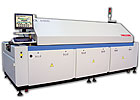
As with printing and placement, specialized equipment may be necessary to reflow large boards. Reflow ovens with 22-inch-wide conveyors and center supports are available. Because big boards can absorb large amounts of heat, they need a powerful oven that can respond quickly to temperature changes. For even heating, forced convection ovens are better for large boards than infrared models. The cooling system must also be efficient, because big boards take longer to cool than small ones.In most cases, however, oven capacity is less of an issue with reflow than the ability to develop an adequate profile. “These boards are thick, with a lot of ground planes, so profiling is more difficult,” says Larry Moon, applications engineer with Juki Automation Systems Inc. (Morrisville, NC).
“One good thing about a large board is that you have the ability to distribute heat more uniformly, because it’s such a big heat sink,” adds Baggio. “The panel may be more difficult to heat up initially, but you often have better control over the temperature gradients across the board.
“Of course, it depends on the components. Large boards are usually infrastructure products, and they tend to have components that require a large amount of very localized heat. Smaller boards are more densely populated, so the heat mass is more evenly distributed.”
On the down side, optimal utilization of the oven is a concern, since large boards are typically produced in small lots. “The issue is how long the oven takes to go from one profile to another,” says Baggio. “The way to mitigate that is to keep the temperature recipe as close to constant as possible, but change the oven speed.”
