Analyzing Bolted Joints for Clamp Load and Joint Stress
Bolts generate a lot of clamp load in a small area. That’s good for tight joints, but it can also create stress.
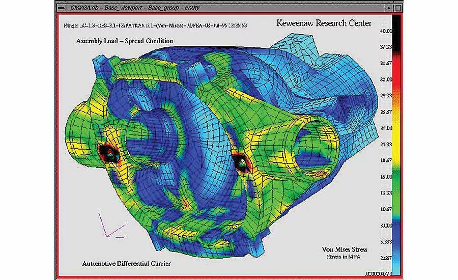
Figure 1. This screen capture shows FEA analysis of an automotive differential housing under expected loading. As is often the case, the highest stress is due to bolt tension (in this case acting on the two the tapped holes). Photo courtesy Keweenaw Research Center
This graph compares contact pressure vs. compressive yield strength for a hex-head cap screw and a flange-head cap screw. Contact pressure regions are based on the assumption of uniform loading of 75 percent of minimum proof load on contact areas of 0.18 and 0.52 square inch. The upper and lower edge of each region is the pressure exerted by a Grade 8 and Grade 5 screw, respectively. Source: Peak Innovations Engineering
These scans of pressure-sensitive film show the pressure distribution under the head of a ½-inch bolt tensioned to 5,000 pounds. Photo courtesy Peak Innovations Engineering
These photos of pressure-sensitive film show the pressure distribution across the bearing surface of a hex flange nut (top) and hex flange cap screws from two different suppliers (middle and bottom). This study was undertaken when the hex flange screw used in Figure 3 unexpectedly showed pressure concentrated at the edge of the clearance hole rather than outside diameter of the flange. Photo courtesy Peak Innovations Engineering
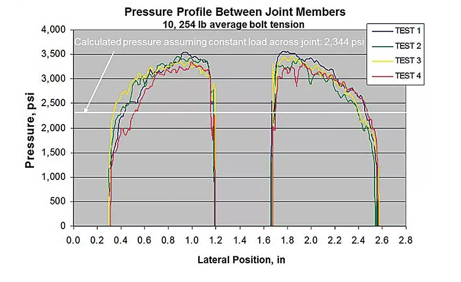
This graph illustrates the problem of uneven clamp load by showing the pressure distribution across two cylinders (2.25 inches in diameter and 2 inches long) clamped by a ½ inch-13 screw and nut. Even at this thickness, the peak pressure is still 40 percent greater than would be predicted by dividing the bolt tension by the contact area at the joint faces. Graph courtesy Peak Innovations Engineering

This FEA analysis shows the stress in mating screw threads. Source: “Stress Analysis of Bolted Joints,” László Molnár, et. al.

Figure 7. This graph summarizes estimated thread engagement relative to the nominal fastener diameter for a number of common nut member materials. Photo courtesy Peak Innovations Engineering
Many important considerations in bolted joint development are often overlooked. While estimating the bolt tension achieved for a given tightening strategy is certainly a common focus, the effect of load on joint components is less fully discussed and understood.
One reason threaded fasteners are so widely used is that they can generate a tremendous amount of clamp load in a small area. Clamp load is central because it is the mechanism by which joint components are held together without moving relative to one another—arguably the primary requirement of a structural joint. However, placing a large load on a small area creates a high level of stress, which, in turn, can lead to problems. For example, a ½ - 20 Grade 8 bolt can supply nearly 20,000 pounds of clamp load. A standard hex head bearing on a standard 9/16-inch clearance hole means all that load would act on an area only half the size of a dime. The resulting stress exceeds the yield strength of most materials. An analogy is the effect spike heels can have on wood floors.
This article will examine the impact of bolt tension on the two opposing areas over which that load is distributed—under the head or nut and in the mating threads. For example, Figure 1 shows a finite element analysis (FEA) of an automotive differential housing. As is often the case, the highest stresses act on the threaded holes.
Under the Bolt Head and Nut
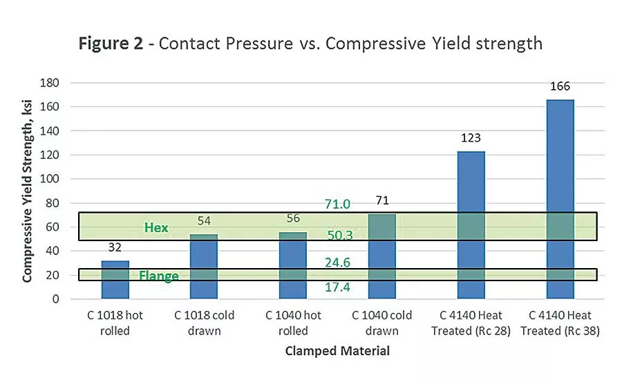
With the exception of not testing to determine bolt tension and the resulting clamp load, exceeding the compressive yield strength of the material under the bolt head or nut is the most common deviation from recommended design practice. The most common target for bolt tightening is to achieve 75 percent of the bolt’s proof load. Using a ½-13 hex-head cap screw for illustration, Figure 2 summarizes the pressure that would be generated by that bolt tension on the mating material, assuming a standard 9/16-inch clearance hole. It then compares that pressure to the estimated compressive yield strength of common steel clamp members with a range of hardness.
Note that compressive yield strength is rarely specified, but tensile yield strength is a commonly accepted estimate for some materials, such as steel, though not others (notably, all types of cast iron). To show how relatively small dimensional changes can have great impact on area, the same calculation is performed for a flange-head screw. Use of flat washers is not included, because the calculation would depend on the relative hardness of the washer, clamped member and fastener, as well as the inside and outside diameter of the washer.
The take-away from Figure 2 is that as long as Grade 8 fasteners aren’t used on materials softer than the Rockwell C scale, the area under hex-head fasteners is sufficient. Unfortunately, the actual pressure is highly uneven, and contact area is often less than predicted due to uneven surfaces. Therefore, the maximum actual pressure is much higher than the theoretical average value.
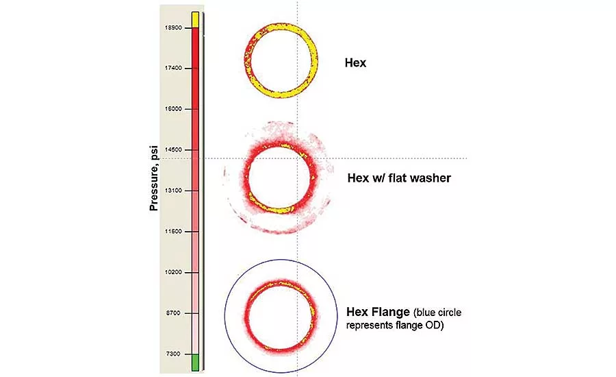
Figure 3 shows scanned images of pressure-sensitive film placed directly under the head of a hex cap screw and under a combination hex cap screw head and flat washer. The standard washer’s thickness is not nearly great enough to distribute loads evenly across its diameter. Note that a hardened washer of the same dimensions would behave the same way. Of course, there are reasons to use flat washers other than to spread bolt loads, such as providing a constant friction coefficient against varying clamp materials and finishes, eliminating galling or stick-slip, and protecting the integrity of the underlying finish.
Looking for quick answers on assembly and manufacturing topics? Try Ask ASM, our new smart AI search tool. Ask ASM
While flange heads are stiffer than standard flat washers, a different variable must be considered. The contact face is not perfectly flat, but instead slightly conical. This creates a different type of pressure gradient across the diameter, and one that is more difficult to predict.
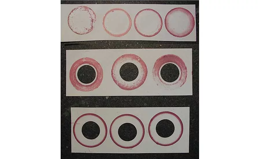
This is illustrated in Figure 4, which shows photos of pressure-sensitive film studies of flange nuts and screws. This review of ½ inch and M12 flange hardware was undertaken when a customer test discovered a flange-head screw with a convex surface (contact at the edge of the clearance hole). An example is shown in the bottom image of Figure 3. In addition to increasing surface area, increasing the contact diameter of the fastener increases frictional resistance to applied torque. This reduces the bolt tension generated for a given torque. In this case, the tension reduction of substituting flange-head for hex-head fasteners is approximately 12 percent.
Figure 5 extends this example of uneven clamp load by showing the pressure distribution across two cylinders (2.25 inches in diameter and 2 inches long) clamped by a ½ inch-13 screw and nut. Even at this thickness, the peak pressure is still 40 percent greater than would be predicted by dividing the bolt tension by the contact area at the joint faces.
This discussion is not intended to imply that compressive yield (commonly referred to as embedment) should be avoided at all times. In many instances, the reduction in clamp load required to prevent embedment would be more detrimental to reliability than the relaxation caused by yield of high-stress areas. I’m only suggesting that this is an area that deserves more attention, through preliminary calculation and subsequent testing.
Some situations that require particular attention include:
Joints with significant embedment that are regularly serviced. Subsequent bolt installation may have greatly reduced and uneven contact areas, leading to increased potential for fatigue failure due to bolt bending and clamp load loss.
Joints that combine high axial loads and bolts with small length-to-diameter ratios. In joints where compressive yield is imminent, the additional bolt load can be great enough to create much more clamp load loss than the relaxation that regularly occurs due to localized yield immediately after tightening.
Joints operating at temperatures significantly different than those at which tightening occurred, especially those that also have clamped members with different rates of thermal expansion than the bolts. A common example is engine bolts in aluminum castings. At operating temperature, the greater expansion of the aluminum castings can result in clamp load loss through embedment, bolt yield or thread yield.
Thread Area
The fundamental issue in distributing bolt tension within the mating threads is the same as that with the head or nut face: That a large load must be dissipated over a small area. Two factors make the threaded area potentially more problematic. First is that the internal threads are sometimes provided as separate standardized elements (nuts) and sometimes by the manufacturer’s design (tapped holes).
Secondly, the forces in the threads don’t act normal to the mating surfaces, as under the head and nut face. The triangular thread form results in forces that both compress and expand the internal threads. This effect can be seen in Figure 6, an FEA screenshot of stresses on a typical nut and mating threads. As with the load under the bearing surfaces, load along the length of threads is not uniform. Studies show the first engaged thread absorbs about one-third of the bolt tension. The remaining tension is absorbed in ever-smaller amounts by the remaining threads, until all the load is effectively absorbed by the sixth thread.
This should raise the question as to why some tapped holes have significantly more than six threads. Because the material into which holes are tapped often has less strength than the mating screw, that material can yield before the screw does. Looking at Figure 6, one can imagine if the surface of the most highly stressed thread crushed even minutely, load would then be transferred down the line of threads, causing partial leveling of individual thread stress. This is how additional threads are engaged.
To a lesser degree, this effect is present in standard nuts properly matched with the mating screw. Nuts are specified to have slightly lower yield strength that the matched screw to take advantage of this effect. It is important to note that this doesn’t mean the nut is the weaker of the two elements, as its height is established so that there is enough thread area that the bolt will fracture before the nut threads suffer noticeable damage.
The width or diameter of the nut also plays a part in its load capacity. Figure 6 shows the nut threads expanding away from the screw as mating threads slide relative to one another radially. This reduction in thread engagement, and therefore load capacity, is a function of the nut member’s stiffness in the radial direction. Width across the flats of standard nuts is about 1.5 to 1.6 times the nominal thread diameter. This is actually a compromise between strength and size, as a ratio of nearly 2-to-1 is required to eliminate dilation. Nuts are available in larger widths and lengths when required.
A much more isolated, but related, effect can be seen in specialty nuts, such as those used in aerospace. These nuts have a thick flange to minimize dilation, but they have a thin wall above the flange to save weight. This often results in axial compression of the nut body prior to bolt yield.
The most common design challenge on the threaded end of a bolted joint is determining the required thread engagement when using tapped holes. As with nuts, the objective is to ensure that the failure mode in the event of overtightening is by bolt fracture rather than thread strip. This mode is preferable, because it is more obvious (stripped threads don’t generate a loose bolt) and repair is generally less expensive and more dependable.
Figure 7 summarizes estimated thread engagement relative to the nominal fastener diameter for a number of common nut member materials. Ultimate shear strength—the material property required to estimate required thread engagement—is generally only available for common materials. However, it is often estimated as a percentage of ultimate tensile strength. While Figure 7 is based on calculations for a single thread size, the length-to-diameter ratio remains within about 5 percent across the range of fastener diameters, except at the small end (under ¼ inch or M6).
In addition, this calculation doesn’t account for common features, such as:
The incomplete threads at the screw tip in blind holes. This can reduce capacity by 20 percent in hard materials that require only short thread engagement.
The chamfer added to the hole entry after tapping. This is often incorrectly included in thread engagement. Because it is often not seen as an important dimension, and because it is difficult to measure accurately, this feature is often not well controlled. As with incomplete threads, the impact is greater the smaller the length-to-diameter ratio.
Because the radial dimensions of thread engagement are quite small, small dimensional changes in either internal or external threads can have a measurable impact on load capacity. For example, if all the dimensional and material tolerances on standard threads are at a worst-case condition, failure mode can change bolt fracture to thread strip. Dimensional variation is more common in tapped holes, particularly by those produced by lower volume production methods, than in standard fasteners.
In summary, the high stresses produced in bolted joints magnify the effect of “theory vs. reality.” While increasingly powerful analytical tools reduce development time and cost, physical testing of bolted joints is essential to avoid costly failures.
Peak Innovations Engineering focuses exclusively on assisting clients with the development, testing and validation of bolted joints. For more information, call 815-847-7722 or visit http://pieng.com.
Looking for a reprint of this article?
From high-res PDFs to custom plaques, order your copy today!


