Harness Failures: What’s to Blame?
When a wire harness fails, the testing system must be able to quickly pinpoint where and why it happened.
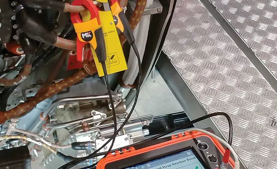
Harness technicians at Boeing, Airbus and other aerospace manufacturers use the B-LRT tester to quickly find unreliable ground circuits in aircraft. Photo courtesy MK Test Systems Americas
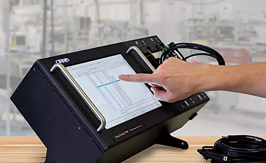
The Easy Touch Pro cable tester accurately tests resistors, diodes, capacitors, LEDs, switches and twisted pairs for opens, shorts and miswires. Photo courtesy Cirris Systems Corp.
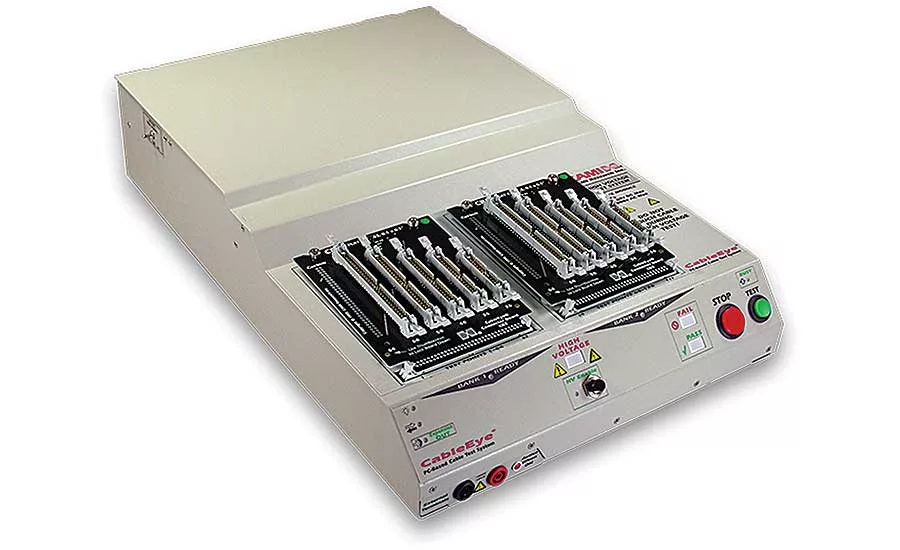
Harness manufacturers can meet industry-standard A620B testing guidelines with the HVX-21 high-voltage tester, which has a current sensitivity of 0.1 microamp and maximum test voltage of 2,100 VDC. Photo courtesy CAMI Research Inc.
Taking tests and waiting with hope for positive results is a stressful activity that most people perform only when absolutely necessary. For wire-harness assemblers, it’s a daily challenge.
During assembly, they’re required to correctly insert one wire into the corresponding connector before they can go on to the next wire. And after building the harness, the assemblers are hopeful that electrical-test equipment will tell them the harness is error-free—even though they may find out that the harness has failed.
“Test system data and statistical process control are both crucial to finding the root cause of any harness failure and preventing it in the future,” says Joe Kane, regional director at MK Test Systems Americas. “This statement applies to every application, whether it’s testing a single wire with two points, or testing an intricate harness with tens of thousands of points.”
A couple years ago, MK Test Systems developed the B-LRT tester to help harness technicians at Boeing, Airbus and other aerospace manufacturers quickly find unreliable ground circuits in aircraft. Such circuits leave aircraft vulnerable to the damaging effects of stray currents, lightning strikes and high-intensity radiated fields.
Kane says the B-LRT tester quickly performs bond, loop and joint resistance tests, and it guarantees accurate measurements. Built-in software guides the operator via easy-to-understand graphics and test instructions. All results are automatically recorded and uploaded to the facility’s main server via a Wi-Fi, LAN or portable storage device.
The bond test measures the electrical resistance between two joined metallic elements. For the loop test, a number of metallic elements and equipment are connected to create a loop of parallel resistance paths. The technician places clamps on each side of the loop. One injects current into the loop, while the other detects the current flowing in the loop. The joint resistance test also makes use of the loop test current. As current is injected, voltage is dropped and then phase-corrected to determine joint resistance.
“A typical single-aisle aircraft requires around 800 bonding measurements in each wing and 400 in the engine,” explains Kane. “It’s common for the total number of tests per aircraft to run into the thousands.”
Looking for quick answers on assembly and manufacturing topics? Try Ask ASM, our new smart AI search tool. Ask ASM
The B-LRT is just one of many state-of-the-art products technicians use to test wire harnesses. Some are hardware- or software-based, while others make it easier to connect a harness to a tester. Their ultimate goal is the same, however: help manufacturers improve harness quality by pinpointing current failures and preventing future ones.
Much Better Than a Buzz
Manufacturers have used wires or harnesses in their products for more than a century, but initially the companies emphasized troubleshooting rather than testing. Throughout the first decades of the 20th century, each wire was tested with a go—no-go system. Multimeter probes were placed on the two points of a wire, or the points were run through a light bulb for continuity. A good wire produced either a buzz or a light.
As harnesses evolved in complexity, so did the need for testing. By the 1950s, harness manufacturers—particularly those serving the automotive industry—began using telephone stepper switches (relays) to test the continuity of each harness wire and verify its location in a connector.
Testing was fairly slow, and remained so until electronic switches began being used in the late 1980s. Today’s standard continuity tester, for example, can test 1,000 wire points in 3 seconds. Thirty years ago, the tester needed a minute or more.
Continuity testing is one of the main tests performed by low-voltage (LV) testers. These machines also detect and actuate harness components, including relays, sensors, switches, resistors, capacitors, diodes and connectors.
Chris Strangio, founder, president and CEO of CAMI Research Inc., says that LV testers are specifically designed to handle low or high test-point counts. The former are less expensive, used for basic continuity testing of small harnesses and may or may not be able to measure resistance. High-test-point-count units become so by expanding (adding molecules) to a low test-point tester. Irrespective of test point count, both types are powered by the same base unit and software.
High-voltage (HV) testers are often used for hipot (high potential) and dielectric testing, as well as component, insulation resistance, capacitance measurement, continuity and short circuit testing. In a hipot test, 1,000 VDC or more is applied to all test points to see whether or not current flows from one point to another. If no current flows, the test points are properly isolated. HV testers also ensure the integrity of the line, neutral and ground circuits of power cords and appliances.
MK Test’s high-voltage system performs DC and AC hipot and dielectric tests, along with passive and active component testing. It can also do a continuity or short circuit test and resistance measurement in two- and four-wire (Kelvin) mode.
“Besides relying on testers with advanced test capabilities, manufacturers need testers that connect with other equipment and databases,” says Kjell Uddeborg, senior software engineer at Cablescan Inc. “If the company has a database that exports a wire list to an Excel file, this data can be automatically imported into the tester and generate test programs. This saves time and eliminates the possibility of human errors when the technician interprets the data and re-enters it into the tester. Some customers also import ‘netlists’ (electronic-circuit connectivity descriptions) generated by the CAD station used to design the harness.”
Cablescan’s TestRite software creates, edits and previews wire (continuity) list programs on a PC without a tester connected to it. When a tester is connected, the technician can select the ‘learn’ command on the software tool bar to create a program.
The company also makes the 90L8 low-voltage tester, which connects with a Windows-based PC through a USB serial port. This tester is expandable in 128-point increments from 128 to 1,024 test points. It also performs isolation tests at 5 VDC up to 9.5 Mohms, and two- and four-wire continuity tests down to 1 ohm.
Fault Factors
Harnesses fail for several reasons, all of which can be traced back to four main sources: the cable, the fixturing, the tester or the technician. Kevin Ellsworth, product manager at Cirris Systems Corp., notes that if a defective cable is used as the primary cable to create a test program, then all good cables will fail because they are tested using bad test instructions.
The best way to find out if a specific cable is the problem is to run a different cable with the same test program. If you are reasonably confident that both cables should have been correct, but you are getting the same error on both, then it is possible the failure is on the test setup rather than the cables. Another way to affirm this conclusion, according to Ellsworth, is if the original cable passes testing on a different tester.
“Fixturing that is not built and installed correctly can cause test failures,” says Ellsworth. “To determine if fixturing is the cause of failure, create a new test program. If the error still occurs, the problem likely is fixturing, which can be replaced or repaired.”
As for the tester, either its interface (the part of the tester visible to the user) or the unit itself can cause harnesses to fail electrical tests. Problems with the interface sometimes can be repaired by the user, whereas problems with the unit may have to be looked at by the tester supplier. Ellsworth says that various components inside the unit chassis can result in poor operation.
To accurately determine if a specific tester is the problem, inspect it for obvious signs of defects, replace its adapters and verify that no debris (especially metal) is located in the test area. Then analyze cables and fixturing on the tester in question and a different tester, and compare results.
Harness manufacturers often use Cirris’s Easy Touch Pro tester to accurately test resistors, diodes, capacitors, LEDs, switches and twisted pairs for opens, shorts and miswires. The tester runs easy-wire software on a Windows 10 operating system and offers 128 test points per box (1,024 maximum). The self-contained unit handles voltages of 1,500 VDC, and processes data up to three times faster than its predecessor, the Easy Touch. The upgraded model also features a high-resolution, 10.4-inch color touch screen made of
Dragontrail glass (thin, light and damage-resistant).
“There are many ways to determine why a harness fails, including inspection, disassembly, and crimp and solder joint mechanical testing,” says Strangio. “In addition, electrical or mechanical failures can cause the harness to fail a quality inspection.”
Strangio says it’s important that the person administering the test do so flawlessly. This means the person must carefully handle the harness (to avoid insulation nicks, bent pins, etc.), and properly set up the tester, perform all procedures and provide the required labeling and related documentation.
“If the test parameters and procedures are not adequately defined, or the test equipment is improperly set up, the harness may pass when it should fail—and then end up failing while in operation by the end user,” explains Strangio. “The converse scenario is that the harness may fail when it should pass. While less critical, this leads to a loss in productivity. Therefore, it’s always best to investigate each possible root cause when multiple faults are found.”
CAMI’s HVX-21 high-voltage tester has a current sensitivity of 0.1 microamp and maximum test voltage of 2,100 VDC. Designed to meet industry-standard A620B testing guidelines, the tester lets technicians specifically program ramp up, ramp down, dwell time (test time), trip current and trip delay (soak time) for each application. It also produces archival-quality reports for each cable tested that clearly says ‘pass’ or ‘fail’ at the top. Each report includes data such as test voltage, leakage current and insulation resistance for each wire group.
“The best way to determine why a harness has failed can vary quite a bit from application to application,” concludes Uddeborg. “You can be fairly confident that small harnesses that pass testing through the ‘learn-known good’ process are wired correctly. For large harnesses, though, it’s getting increasingly harder to be sure. These harnesses are often better tested using programs created from Excel sheets or CAD data.”
Will Topology Diagnostics Lessen Wiring Headaches?
This past February, MAHLE Service Solutions introduced Topology Diagnostics (TD) software, which provides technicians with 2D topology diagrams that immediately display prioritized wire harness failure areas on vehicles that have failed end-of-line testing. Mohan Sethi, business development manager at MAHLE, says at least one automotive OEM plans to implement the software during the first half of this year after completing a test trial.
“A technician runs the software, and within seconds, sees a topology diagram that is vehicle specific and displays a prioritized list of connectors that may be causing the fault,” explains Sethi. “The software shows the technician the connectors, pinouts, wire-colors and potentially 3D component locations of where the problem may be. This eliminates the need for time-consuming review of complex wiring diagrams and diagnostics that require tearing apart multiple systems to find wiring problems.”
According to Andreas Huber, general manager at MAHLE, TD requires no special hardware or connections to access the vehicle. When the software runs, it quickly detects module-level ‘no communication’ errors and diagnostic trouble code failure. It also provides analysis of the problems.
“Technicians are provided a quick diagnosis of the problem, and a simplified-view diagram with pin numbers,” says Huber. “The prioritized list of connectors to check is based on circuit logic with a ‘probable cause’ of failure integrated into connector priority.”
Sethi says that MAHLE trains technicians at the plant on how to use the software, and that the company plans to introduce the software to the repair side of the automotive industry in the near future. MAHLE developed the software in partnership with Tweddle Group, a technical information services firm. MAHLE Service Solutions is a division of MAHLE Aftermarket Inc.
Looking for a reprint of this article?
From high-res PDFs to custom plaques, order your copy today!


