advertisement
How To Guide Robotic Arms for Random Bin Picking
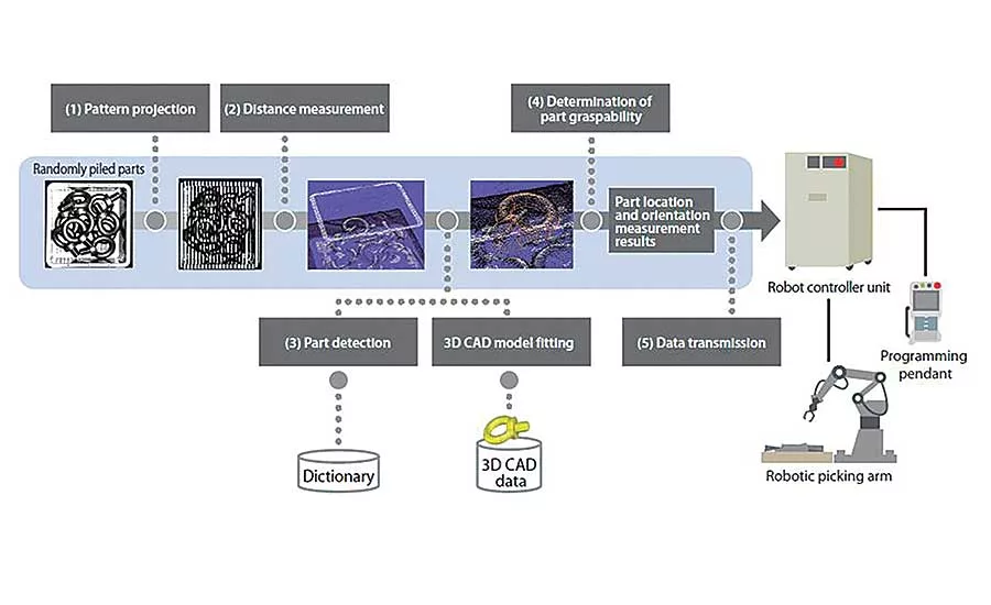

Workflow of 3D Recognition
1) Various Patterns are projected onto randomly piled parts
2) The distance between the randomly piled parts and the sensor is measured
3) A pre-registered pattern dictionary and 3d CAD models are used to recognized part positioning without making contact with other parts
4) The system determines if the robot hand can grasp the part without making contact with other parts
5) Data is sent to the robot controller unit
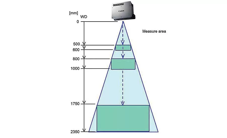
Measurement Area
Users can easily register data for parts to be picked up by inputting CAD data and by capturing images of the parts randomly assembled in a pile. The 3‐D machine vision systems can use computer‐generated images to automatically learn how to visually identify the parts. Since no complicated programming is necessary, users can easily re‐register parts in accordance with changes in type and shape of parts to be supplied in production Depending upon the size of parts, there are currently 3 models are available with a high level of accuracy; the RV300, RV500, and RV1100 achieve exceedingly small error tolerances of less than 0.1 mm2, 0.15 mm2, 0.5mm2, respectively.
Looking for quick answers on assembly and manufacturing topics? Try Ask ASM, our new smart AI search tool. Ask ASM
Looking for a reprint of this article?
From high-res PDFs to custom plaques, order your copy today!


