Simulation Software Helps AGCO Smooth Out Equipment Design Process
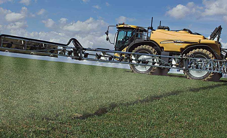
The Challenger RoGator 600 series crop sprayer has a boom length of 36 meters. Photo courtesy AGCO Corp.
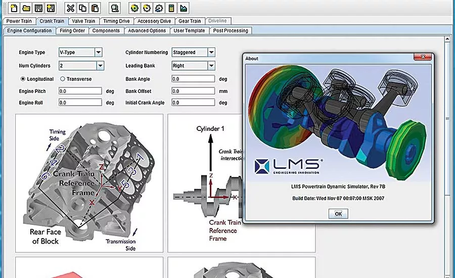
LMS Virtual.Lab Motion modeling software simulates full-motion behavior of complex mechatronic systems. Graphic courtesy Siemens PLM Software
Crop sprayers play a vital role in professional farm management. Farmers and farming contractors rely on this equipment to evenly apply exact amounts of nutrients and protectants on hundreds of acres on demand—although it’s not as easy as it sounds.
Chemicals are pumped from large tanks to tiny nozzles along wide booms that span across multiple rows of crops. The tanks can hold thousands of liters of fluid, and the booms can be many meters in length. In addition, operators must maneuver sharp turns at the end of crop rows, where big bumps can cause fatigue cracks in the equipment, and a small bounce may result in uneven or spotty spray.
Netherlands-based AGCO Corp. has been manufacturing crop sprayers for decades. In 2014, company engineers decided to redesign AGCO’s latest self-propelled crop sprayer: the Challenger RoGator 600 series.
“What we heard from large-scale farmers and contractors all over Europe was that a smooth ride was essential to spray performance. Speed and boom reach [were also important],” explains Joris Hiddema, engineering manager for sprayers at AGCO. “We realized that just touching-up our old design wouldn’t work. We needed an unconventional design approach.”
The Challenger RoGator travels up to 30 kilometers per hour and has a boom length of 36 meters. It features a boom suspension system with an all-steel central frame and cantilevered truss beams made of tubular aluminum to save weight.
“We worked with the learning management system (LMS) experts from Siemens PLM Software to tune each spring-damper pair for ideal handling of extreme horizontal, vertical and yaw boom movements,” explains Hiddema. “The project required detailed evaluation of the boom suspension, as well as all vehicle dynamics. This was critical for boom stability.”
The LMS Engineering (LMSE) team extracted the dimensions and mass of the boom arms, the central frame and pendulum suspension. Next, they used LMS Virtual.Lab Motion (VLM) software to create a multibody model of the frame and pendulum. The team later created a finite element model of the boom arms and performed a modal analysis.
Looking for quick answers on assembly and manufacturing topics? Try Ask ASM, our new smart AI search tool. Ask ASM
“We needed to consider vibrations from the tractor, so the entire vehicle was modeled, including independent wheel suspensions, the steering system, the cabin and all the joints: spherical, revolute and cylindrical ones,” says Hiddema. “Mass and inertial properties were calculated from CAD data. Tires were represented in a VLM model to determine tire-induced vibrations. Pendulum suspension kinematics were checked for potential interference such as joint lockups.”
LMSE also performed a multi-body VLM simulation to check the boom response at various speeds and maneuvers. This simulation provided the right information to fine-tune the dampers and springs, and properly position the components.
To accurately build the sprayer prototype, performance traits were measured using LMS SCADAS Mobile hardware for data acquisition and LMS Test.Lab software for data analysis. All horizontal, vertical and yaw displacements closely matched those predicted with multi-body dynamics simulation.
AGCO was also happy to learn that LMSE significantly reduced the coefficient of variation (CV) of the sprayer’s distribution pattern to about 5 percent. This rating is based on a system from the Germany-based Julius Kühn Institute, which regards a CV of 15 to 20 as acceptable and below 10 as exceptional.
For more information on LMS software, call 800-498-5351 or visit www.plm.automation.siemens.com.
Looking for a reprint of this article?
From high-res PDFs to custom plaques, order your copy today!


