SWITCHES & RELAYS: Cut the Chatter
Recent developments in electronic equipment have led to technically advanced appliances that require progressive electronic technologies. Today's equipment is required to perform multiple functions in limited size due its use of integrated circuit and microcomputer technology. Therefore, the components must be miniaturized and lightweight. As a result, functional limits of electromechanical relays have narrowed due to increasing contact amperage in smaller packages.
Relays are electrically controlled devices that open or close electrical contacts to affect the operation of other devices in the same or different circuits. A relay's most basic components are its coil, armature, and contacts. When the relay is put into a given circuit, the current from that circuit induces a magnetic field in the relay coil. The magnetic field then affects the armature in such a fashion that it causes the contacts to make or break the part of the circuit that is attached to the relay output.
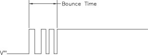
Fig. 1. Typical contact bounce.
When a pair of contacts closes and makes the circuit, there is a mechanical impact between them and they rebound and bounce. This is sometimes referred to as "contact chatter." The diagram in Fig. 1 demonstrates a typical "contact bounce" trace utilizing a DC load. For the purpose of this article, "contact bounce" and "contact chatter" are going to be separated into two different phenomena that can occur within electromechanical relays. As previously stated, contact bounce and contact chatter are often referred to as the same thing. However, contact bounce is the uncontrolled opening and closing of the contacts due to forces within the relay (internal forces), whereas contact chatter is the uncontrolled opening and closing of contacts due to external forces.
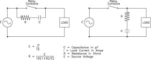
Fig. 2. RC Network. Circuit A at left. Circuit B at right.
Contact bounce
The amount of contact bounce is dependent on, and an inherent part of, the design of the relay. The closing velocity of the contacts, the initial contact force, the mass of the contacts, and mechanical resonances in the contact system, all have an impact on the amount of contact bounce that is generated during contact closure. When using load levels and types that do not generate arcing, contact bounce does not shorten the life of the contacts, although it may be undesirable when the associated circuitry would sense these added openings and closings.
However, when an arc is present, contact bounce can lower the life expectancy of the relay or cause welding of the contacts. Contact bounce is also capable of inducing oscillations of several kilohertz, contact arcing frequencies of several megahertz and, in the case of reactive loads, amplitudes 10 to 100 times the normal circuit voltages or more.
A method of reducing the impact that contact bounce may have is to employ a contact protection circuit. One common protection circuit is a resistor - capacitor (RC) network, as shown in Fig. 2.
In Circuit A, the impedance of the load should be smaller than the RC circuit's impedance. Circuit A should not be utilized for timer loads, as the leakage current can cause faulty operation. In Circuit B, the release time may be lengthened if the load is another relay or solenoid.
Looking for quick answers on assembly and manufacturing topics? Try Ask ASM, our new smart AI search tool. Ask ASM
The RC combination absorbs the high-energy oscillations caused by the contact bounce. Similarly, the oscillations created by the arcing are averaged and suppressed by the RC combination. This RC network will also help suppress the arc during the contact break operation and increase the overall life of the relay. The formulas set forth above are used as a starting point when determining the resistance and capacitance needed for the RC network. As always, the final selection should be evaluated in the application to determine its acceptability.
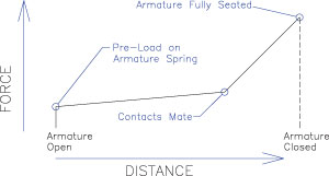
Fig. 3. Typical force distance plot.
Contact chatter
Contact chatter is extended contact bounce that is not an inherent part of the relay. Contact chatter usually occurs because of either shock or vibration to the relay or an improper control signal to the relay. For the purpose of this discussion, the primary focus is on the control signal to the relay.
A control voltage is applied to the coil of the relay in order for the relay to operate. The relay has a minimum voltage that provides proper actuation of the relay contacts. If the control voltage drops below the specified minimum operating voltage, the relay may chatter. This rapid on and off cycling of the contacts occurs continuously for several seconds, causing excessive heating of the contacts and resulting in severe damage to the relay contacts. This low-voltage chatter condition occurs due to the insufficient pull of the magnet at low voltages to overcome the spring forces that are needed to operate the relay effectively. A typical force-distance plot of a relay is shown in Fig. 3.
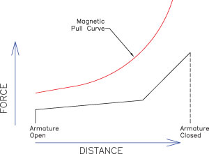
Fig. 4. Force distance curve with magnet pull curve.
The armature spring keeps the contacts open when there is no voltage applied to the coil and opens the contacts when the voltage is removed from the coil. When voltage is applied to the coil, the armature starts to close and the armature spring force increases until the moveable contact touches the stationary contact. At this point the armature spring force is combined with the contact spring force. This total force increases until the armature is fully seated. When the voltage applied to the relay coil is above the minimum requirement, the pull force of the magnet is greater than the spring force and the relay operates normally. Fig. 4 shows the force-distance curve of the relay along with the pull curve of the magnet.
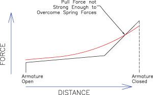
Fig. 5. Contact chatter due to low pick-up voltage.
The force of the pull curve is above the force of the springs throughout the full stroke of the relay. At a voltage lower than the specified pick-up voltage, the pull force of the magnet is not strong enough to overcome the spring force of the relay once the contact spring is activated. At this point, the relay contacts will chatter and remain chattering as long as the low voltage continues. See Fig. 5.
One factor that should be considered with regard to contact chatter is the inrush current of the relay coil. The coil current is higher than the rated current when the relay initially operates. This inrush current, although brief, can drop the voltage significantly if an inadequate source of power is supplied to the coil.
The coil temperature rise of the relay may also have an impact on contact chatter. The coil heats up due to resistive heating of the wire, resistive heating in the shading coil, eddy-current losses in the magnetic circuit, hysteresis losses and contact current heating internal components of the relay. This temperature rise along with the ambient temperature will increase the coil resistance and thus increase the required pick-up voltage of the relay. This effectively is equivalent to lowering the control voltage.
Other factors that may cause chatter are other components that are in the control circuit. These components could either drop the voltage to the relay or cause an intermittent voltage. For example, a pressure switch or proximity switch in the circuit has a trip point that can cause the switch to cycle on and off intermittently. This will turn the relay on and off very rapidly, causing the contacts to chatter.
When dealing with low-voltage chatter, the designer needs to confirm that the specified operating characteristics of the relay are met. The specified minimum must-operate voltage for the relay must be known. Care should be taken when sizing the control transformer or power supply and specifying the proper control wire size such that the control voltage must not be capable of going below this minimum requirement. The designer also needs to take into consideration the ambient temperature in which the relay will operate and how this ambient and the temperature rise of the relay coil previously discussed, will impact the pick-up voltage. Contact bounce is largely an inherent design feature of the relay and can be affected by applied coil voltage.
Contact chatter, on the other hand, is a direct function of shock and vibration applied to the relay, a function of rapid intermittent coil power, or below minimum required coil drive voltage. Contact chatter especially can result in premature erosion of contact material to the point of failure or in welding of the contacts. Control designers must confirm that proper coil drive is always provided regardless of ambient temperature so that neither excessive bounce nor chatter occurs.
Looking for a reprint of this article?
From high-res PDFs to custom plaques, order your copy today!