Assembly Magazine logo
search
Ask ASSEMBLY AI
cart
facebook twitter linkedin youtube
  • Sign In
  • Create Account
  • Sign Out
  • My Account
Assembly Magazine logo
  • TRENDS
    • Ask ASSEMBLY AI
    • Trends
    • News
    • New Products
  • INDUSTRIES
    • Aerospace
    • Appliance
    • DFMA Assembly
    • Medical Devices
    • Green Manufacturing
    • Lean Manufacturing
    • Machinery Assembly
    • Electronics Assembly
    • Automotive
  • TECHNOLOGIES
    • Adhesives & Dispensing
    • Assembly Presses
    • Automated Assembly Systems
    • Manufacturing Management
    • Manufacturing Software
    • Motion Control
    • Screwdriving & Riveting
    • Robotics
    • Test & Inspection
    • Plastics & Metal Welding
    • Wire Processing
    • Workstations
  • AUTONOMOUS & ELECTRIC MOBILITY
    • AEM Magazine Archives
    • Autonomy
    • Electrification
    • Mobility Services
    • Assembly & Testing
    • AV/EM News
  • MEDIA
    • Ask ASSEMBLY AI
    • Podcasts
    • Assembly News Now
    • Assembly TV
    • Webinars
    • eBooks
  • EVENTS
    • Calendar
    • The ASSEMBLY Show
  • MORE
    • Exclusives >
      • Plant of the Year
      • Capital Spending
    • Buyers Guide >
      • Supplier Insights
    • Classifieds
    • Featured Products
    • Newsletters
    • Store
    • White Papers
    • Columns
    • Sponsor Insights
  • INFOCENTER
    • Assembly & Test Solutions
  • EMAGAZINE
    • eMagazine
    • Archive Issues
    • Advertise
    • Contact Us
    • Sign Up
IndustriesAppliance Assembly

SWITCHES & RELAYS: High Reliability at Low Loads

November 1, 2005
Relays switching at minimal loads require clean contacts.

Electromechanical relays are known for their reliability and cost effectiveness. Recent trends include the miniaturization of electromechanical relays, increased quality standards, better reliability and lower cost.

Not only have relay designs changed, but also applications are more diverse. In modern electronics, signal levels decrease while system impedance increases. Therefore, relay contacts are operated at low or dry circuit levels with small currents. No arcing occurs to clean the contacts and due to circuit requirements, load levels of varying magnitude are applied to the same relay. One contact system is used to switch the load; the other is used for monitoring purposes.

Fig. 1: Results obtained from an electrical endurance test (Contact application 0, ≤30 mV/≤10 mA), 100 million operations. The graph (shown at top) represents the minimum, average and maximum values obtained from 20 gold contacts, which gives 600 million data points in total.
Circuits with low loads and voltages in the µV range and currents even in the nA range are trending up in electronics and industrial control. Also, more load switching and monitoring circuits in parallel in the same device occurs. Other trends include:

  • Switching of load and monitoring circuits in sequence.
  • High loads applied in signal and low loads for power relays.
  • Diverse temperature and environmental operating conditions.

    Fig. 2a: Characteristic contact resistance of AgNi 0.15 break contacts tested in a commercial relay. Load 10 V/100 mA. (Above)

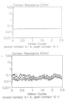
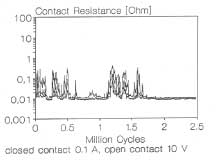
    Fig. 2b: Characteristic contact resistance of AgCdO10 contacts tested in a commercial relay. Load 10 V/100 mA. (Below)

    Low-level loads

    The term "minimum load" should be clearly defined since load ranges vary greatly for the wide range of applications where relays are used.

    Load & Voltage Definitions/Ranges

  • Dry circuit is defined by 0

    Fig. 3. Characteristic contact resistance of AgSnO2 8 break contacts tested in a commercial relay. Load 10 V/100 mA.
    Low Loads. Two issues are important for low loads. First, during contact break, the temperature in the constriction area increases to the melting and then boiling temperature of the contact material. Even though the open circuit voltage is lower than the minimum arc voltage, short arcs with low energy still occur due to inherent inductance and capacitance. Consequentially, carbon forms on the contacts (due to atmospheric hydrocarbons). The arc does not have enough energy to remove the carbon, though. Typically, carbon or carbonized contacts have contact resistance between 2 and 4 Ohms.

    Intermediate Loads. For intermediate loads, short arcs and discharges from cables are the most common effects. If the arc has enough energy to burn the carbon on the contacts, contact erosion can occur.

    High Loads - Arcing Contacts. On practically all high loads, arcing can be detected. Depending on the voltage and current, switched contact erosion or material transfer is the main effect. Depending on the load applied, erosion or transfer of contact material are the visible results.

    Mixed level switching. In different applications, monitoring the contact position in the load circuit is required. The tight and failsafe coupling between two different contacts is realized in safety relays by applying forcibly guided contacts. For example, one contact is used to switch the load, and another is in the load circuit. The power in the load circuit depends on the application and variants between mW and kW (kVA). The control circuit(s) is normally on the logic level of devices such as FPGA or ASICs. A frequent issue is the separating contacts connected to power from those connected to the control circuit. The switching arc produces a splash of oxides and carbon particles which disperse in the area (for example, the contacts on which the control signal is carried).

    Fig. 4. Parameters defining the minimum load for gold contacts.

    Requirements

    When switching devices have to carry and switch low level loads, certain considerations must be made to help provide for optimum performance. Firstly, the switching device must have contacts that are clean. Secondly, the switching devices must be properly protected from external particles such as dust and corrosion.

    Contact Cleanliness. In order determine the suitability of contact materials for certain loads, (i.e. to determine the minimum load they are suitable to switch) the contact surface must be clean and its condition known. In the relay industry, there are two strategies used to achieve defined conditions. Whether contamination is present during manufacturing or the cleaning process is applied in order to remove contamination from the relay. The first approach is more reliable and results in higher quality relays.

    Protection of Relays. Two standards are commonly referenced for protection of electrical devices against external influences. While IEC60529 defines the degrees of protection provided by enclosures (IP code), the more suitable definition for low-level switching devices is the category of protection in IEC 61810-7 which defines the categories as follows:

  • RT 0 (unenclosed)
  • RT I (dust protected)
  • RT II (flux proof)
  • RT III (wash tight)
  • RT IV (sealed)
  • RT V (hermetically sealed)

    For low level switching devices, wash tight devices (RTIII) should be chosen, at minimum, in order to provide sufficient protection against external influences.

    Two other issues are of interest in evaluating low level switching. Wash tight relays do not prevent gas exchange between relays and the external atmosphere. In the case of a corrosive environment, hermetically sealed devices should be used. All plastic sealed devices do not protect devices from humidity.

    Environmental Conditions. Generally, low temperature extremes are less critical than high temperatures. Several materials typically used in switching devices such as plastics, have maximum operating temperature limits. When relays are operated with low signals, they operate properly up to a critical temperature. For most organic materials, the critical temperature can be found, when the out gassing products out of the material start to impact the contact resistance values.

    Contact Materials

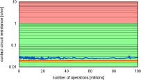
    Silver-Based Contact Materials. These materials are the most commonly used materials. From the performance point of view, the materials can be quite different. Pure silver (Ag) is only suitable for low loads and is not resistant to material transfer. The advantage is high conductivity. Investigations into low level switching performance of different types of silver contact materials revealed characteristic fingerprints of different types of contact materials.

    Silver and Silver Alloys. Silver and silver alloys like AgNi 0.15 show similar performance in commercial relays at low-level switching applications. The contact resistance value is stable and the typical variation of the contact resistance is in the range of a half magnitude.

    Silver Metal Oxides. Many silver metal oxide variations are currently available. AgCdO has been used for years, but is being replaced to comply with various environmental initiatives. AgMeO and AgSnO2 are typical replacements. Since these are heterogeneous materials, the contact resistance stability is less than a homogeneous silver material (Fig. 2 and Fig. 3).

    Gold-Based Contact Materials. Gold alloys for low-level contacts include Au, AuNi, AuPd, AuAg and AuCo. The choice of the material and the required thickness depend on the deposition method, the alloy, the load applied and the protection against external impacts.

    Since pure gold is soft and tends to cold weld, it is seldom used. Therefore, it is alloyed. Often, AuNi (Ni <5%), AuPd (Pd<5%) and AuAg (silver content of up to 10%) are typical. AuCo is for galvanic deposited gold layers.

    Minimum Loads

    Silver Based Contact Materials. In air, silver contact materials may tend to form nonconductive oxides or sulphides. These layers must be removed during contact closing. Relays with silver contacts suitable for low-level loads must be designed in a way that they perform a relative movement when the contacts close.

    So, non-protected relays should not be used for switching low-level loads. At a minimum, a dust-proof (RT I) or higher rated relay housings should protect the contacts. There is not much data available about the minimum possible load available for relays with AgNi0.15, AgNi10 or AgSnO2 contacts, but research continues.

    Tests on 50 relays with AgNi0.15 and AgSnO2 contacts showed after the following:

  • 230VAC/1mA resistive load - 1 million operations. 4230VAC/15mA inductive load - 3 million operations.
  • 5VDC/10mA resistive load -800 000 operations.

    Contact resistance values measured at 10V/10mA were still below 50mOhm.

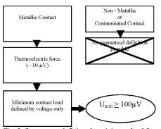
    Gold-Based Contact Materials. Minimum permitted loads when gold contacts are used always apply to dry circuit conditions. Dry circuit applied voltage is roughly 0.08 V. Assuming that clean metallic contacts are used, the only limiting parameter is the thermoelectric force generated - depending on the materials used in the signal path - a small voltage on the contacts. Measurements on commercially available relays with gold contacts showed values less than 10 µV. Therefore; no loads less than approximately 100 µV should be applied to relays with gold contacts.

    Contact Disturbances

    Corrosion Layers. In air, oxides, sulphides and other layers are formed on all metallic surfaces, which increase the contact resistance. As long as the thickness of the layer formed is less than 10 atom layers, there is no change in contact resistance. Thicker layers equal greater resistance. All corrosion layers are insulating or are semiconductors and are insufficient for a technical contact. In order to provide a technical contact this corrosion must be prevented or the corrosion layer must be removed.

    There are two possible ways of removing the layers:

  • Electrical fritting.
  • Mechanically force or relative movement during contact closing.

    Carbon Layers. When contacts are contaminated with hydrocarbons operating in a closed environment and the switch is made of organic materials like plastics, out gassing hydrocarbons can cause the formation of carbon on the contacts.

    The effectiveness of carbon generation depends on:

  • Aliphatic or Cyclic nature and concentration of hydrocarbons.
  • Contact material - carbon generation is 10 times more efficient on Pd than on Au and also 10 times more efficient on Au than on Ag.
  • Load applied - this effect can be observed in a typical load level between 5 V and 2 V, and currents between a few mA and 100 mA.

    When hydrocarbons are absorbed on the contact surface, the low energy arc cracks the hydrocarbons. Since the energy of the arc is not sufficient to burn the carbon it simply remains in the contact area. Typical contact resistance values for carbon can be measured which are in the range of 1Ohm to 2 Ohm.

    SiO2 Coatings. These coatings are formed from silicone when it is present in the contact area and arcing occurs. The organic silicone molecules are oxidized in the arc and form an insulating layer. Since silicone has extreme creeping characteristics, it crosses distances of up to several meters. Tests performed on relays in a silicone atmosphere at a load of 12 V/100 mA showed:

  • Wash tight relays (RT III): SiO2 was formed after some thousand operations.
  • Hermetically sealed relays (RTV): Even after 1 million operation and storage for 1 month, no SiO2 was detected on the contacts.
  • Organic silicones shall not be used in electronics, when switching contacts are involved. If for other reasons silicones are used, only hermetically sealed relays should be used.

    Particles. The biggest enemy of switching electrical contacts are small particles that can prevent the contacts from making contact. Typical sources might be dust when open contacts are used or particles coming from manufacturing processes, and other sources including eroded contacts.

  • Looking for quick answers on assembly and manufacturing topics? Try Ask ASM, our new smart AI search tool. Ask ASM →

    Source: appliance DESIGN

    Share This Story

    Looking for a reprint of this article?
    From high-res PDFs to custom plaques, order your copy today!

    Recommended Content

    JOIN TODAY
    To unlock your recommendations.

    Already have an account? Sign In

    • Made in the U.S.A.

      Consumer Products Manufacturing: Made in the USA

      Supply chain lessons learned during the coronavirus...
      Automated Assembly Systems
      By: Austin Weber
    • Best Practices for Press-Fit Assembly

      Best Practices for Press-Fit Assembly

      In manufacturing, ironclad formulas for success are hard...
      Assembly Presses
      By: Jim Camillo
    • aem0523leader-tesla1.jpg

      Tesla Rethinks the Assembly Line

      Engineers at Tesla Inc. have developed a new process that...
      Automotive Assembly
      By: Austin Weber
    Manage My Account
    • eMagazine Subscription
    • Assembly Newsletters
    • Online Registration
    • Subscription Customer Service
    • Manage My Preferences

    More Videos

    Sponsored Content

    Sponsored Content is a special paid section where industry companies provide high quality, objective, non-commercial content around topics of interest to the ASSEMBLY audience. All Sponsored Content is supplied by the advertising company and any opinions expressed in this article are those of the author and not necessarily reflect the views of ASSEMBLY or its parent company, BNP Media. Interested in participating in our Sponsored Content section? Contact your local rep!

    close
    • ultrasonic welding
      Sponsored bySonobond Ultrasonics

      Engineering Efficiency in High-Performance Assembly: How Ultrasonic Welding Enhances Throughput, Reliability and Quality

    • UV curing system
      Sponsored byDymax

      Why UV Intensity Alone Doesn’t Define Curing Performance

    • wooden pallets
      Sponsored byLEAN Manufacturing Products

      Eliminating Waste on the Shop Floor: Applying Lean Principles to Improve Manufacturing Efficiency

    Popular Stories

    ASSEMBLY News Now, episode-30: Volvo Redesigns EV Manufacturing

    Volvo Redesigns EV Manufacturing

    Boeing CEO Kelly Ortberg announces 1 billion investment

    Boeing Plans $1 Billion Wichita Investment, Workforce Training Center

    automated consumer goods assembly system

    Best Practices for Cycle Time Optimization

    Watch the latest episode of ANN now!

    Events

    July 24, 2025

    From Shop Floor to CFO: How Manufacturers Are Closing the Loop Between Operations and Finance

    On Demand Learn how manufacturers are bridging the gap between the shop floor and ERP systems to gain real-time visibility, streamline operations, and kick-start digital transformation—without waiting years.

    Sponsored by:

    PicoStratusGreen
    July 30, 2025

    Buffer Analysis and Design Fundamentals for Manufacturing Excellence

    On Demand In this presentation, Dr. Herman Tang shares practical insights from his industry experience and research on buffer management in manufacturing operations.

    View All Submit An Event

    Poll

    Difficult Assembly Processes

    Which assembly process gives you the most difficulty?
    View Results Poll Archive

    Products

    Manufacturing Cost Policy Deployment (MCPD) Profitability Scenarios: Systematic and Systemic Improvement of Manufacturing Costs

    Manufacturing Cost Policy Deployment (MCPD) Profitability Scenarios: Systematic and Systemic Improvement of Manufacturing Costs

    See More Products
    Register for webinar - Modernizing Automotive Assembly: Why Upgrading Legacy MES is a Business Imperative

    Related Articles

    • SWITCHES & RELAYS: Cut the Chatter

      See More
    • Meeting the High-Reliability Challenge

      See More
    • HVX line of harness and cable testers

      Tester Measures Leakage at Low Voltage

      See More

    Related Products

    See More Products
    • Reliability Engineering

    • assembly september 2019

      ASSEMBLY September 2019 Issue

    See More Products

    Related Directories

    • Relay

    • Load Cell Central

      Load Cell Central is a leading load cell manufacturer, delivering cutting-edge custom solutions for electronic weighing systems and components, weighing assemblies, and load cell repairs. Our expertise spans a wide range of applications, including the development of custom electronic load cell-based weighing systems, interchangeable replacement load cells, and specialized load cells and weighing assemblies. Whether you're in need of industrial scales, a load cell, or solutions for force measurement, center of gravity, or process and batching control by weight, we are committed to providing innovative, economical solutions. Our approach is comprehensive, guiding clients from the initial concept through to completion, with ongoing support long after the sale. At Load Cell Central, we pride ourselves on our technical expertise, customer-centric approach, and unwavering commitment to quality in every aspect of our service.
    ×

    Never miss the latest news and trends driving the manufacturing industry

    Stay in the know on the latest assembly trends.

    JOIN TODAY!
    • RESOURCES
      • Advertise
      • Contact Us
      • Directories
      • Manufacturing Division
      • Store
      • Want More?
    • SIGN UP TODAY
      • Create Account
      • eMagazine
      • Newsletters
      • Customer Service
      • Manage Preferences
    • SERVICES
      • Marketing Services
      • Reprints
      • Market Research
      • List Rental
      • Survey/Respondent Access
    • STAY CONNECTED
      • LinkedIn
      • Facebook
      • Instagram
      • YouTube
      • X (Twitter)
    • PRIVACY
      • PRIVACY POLICY
      • TERMS & CONDITIONS
      • DO NOT SELL MY PERSONAL INFORMATION
      • PRIVACY REQUEST
      • ACCESSIBILITY

    Copyright ©2026. All Rights Reserved BNP Media, Inc. and BNP Media II, LLC.

    Design, CMS, Hosting & Web Development :: ePublishing