Designing for Efficient Heat Transfer

A step-by-step procedure for optimizing the use of smaller diameter tubes in eco-friendly AC designs.
The steps involved in the design of heat exchangers for air conditioning and refrigeration applications using smaller diameter copper tubes are summarized here. These steps are intended as a general guideline. Specific choices and recommendations are not given here, since such choices may depend upon other components in the system design.
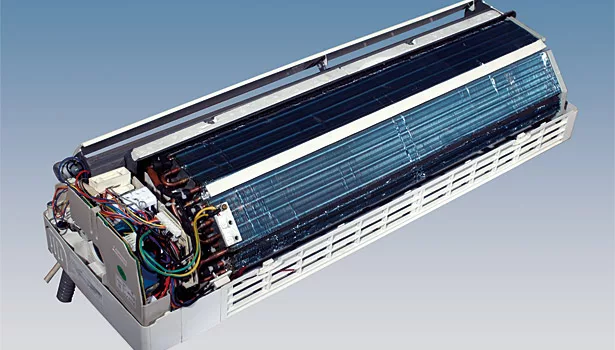
Simply put, an air conditioning or refrigeration system consists of a compressor for work input; and condenser and evaporator coils for heat output and input, respectively. Energy efficiency is dependent upon keeping the refrigerant passing through the condenser and evaporator coils as close as possible to the surrounding outdoor and indoor temperatures, respectively.
Much attention has been focused in recent decades on refrigerants and valves for controlling and regulating refrigerant flow. Yet in the past half a decade, significant advances have also been made in the design of evaporator and condenser coils. These advances have been motivated by the conflicting needs to increase energy efficiency while also reducing materials usage.
It has long been understood that a smaller diameter tube would increase the local heat transfer coefficient (HTC or α) that governs the heat transfer between the refrigerant and the inside of the tube wall. The challenge has been to fabricate smaller diameter tubes and assemble them into heat exchanger coils. The proving ground has been the highly competitive, high volume manufacture of residential air conditioning (RAC) systems, including window-type air conditioners as well as split units. The same design principles apply as well to larger commercial units.
Establishing a Consortium
The ICA sponsors a research and development consortium dedicated to the development of more efficient heat exchanger coils. The consortium includes not only copper tube suppliers but also several major research universities as well as many OEMs who are responsible for a major share of the global production in this product category.
Initially, prototypes were made simply by replacing the larger-diameter copper tubes with smaller diameter copper tubes. The footprint of the heat exchanger in the product was unchanged and the fins in the coil designs were not optimized to the smaller diameter tubes. This could be referred to as the “cut-and-try method.” Nonetheless, the results were immediate and dramatic and this intensified interest in further development.
Consider that if tube diameter is halved then the cross sectional area is cut by 75 percent. Besides reducing the amount of tube material, refrigerant volume could also be reduced. Furthermore, it is well known from tube stress analysis that the burst pressure increases as the tube diameter decreases, hence wall thickness could be decreased, resulting in a further savings of material.
Looking for quick answers on assembly and manufacturing topics? Try Ask ASM, our new smart AI search tool. Ask ASM
Once it was fully understood how smaller-diameter copper tubes provide major competitive advantages, more systematic approaches were taken by the various OEMs in the design and optimization of coils for specific products using various refrigerants.
Tube Pitch Ratio
An evaporator coil or condenser coil is, of course, a component in a system and the tubes and fins are sub-components. The first step toward an optimal heat-exchanger design is to select the tube pitch ratio, which may be quite different for smaller-diameter tubes compared to conventional tubes because the airflow around the tubes is not obstructed as much for smaller tubes.
If there are two rows of tubes then the ratio (Pt /Pl) between transverse and longitudinal tube spacing must be approximated before any further steps can be taken. Initially, values commonly used in heat exchanger designs are selected for fins with high efficiency with operating conditions such as airflow and tube-wall temperature as defined by the applications. The tube pitch ratio is then optimized for the particular application using CFD calculations.
Tube Spacing
How far apart should the tubes be spaced? The outside air pressure drop must be equal to or less than the design criterion; if the tubes are spaced too closely, this air pressure drop may be too high. The objective is to maximize performance while minimizing the cost. An overly large fin size would cost more to manufacture because it uses more fin material. It would also result in a heat exchanger that is larger-than-necessary. For evaporator coils, the condensate film that forms on the fin influences the choice of fin size. Tube spacing dictates the “fin size” that will be used in fin-design simulations.
Fin Design
The next step is to optimize the fin pattern. The two most common types of fin patterns are the louver fin and the slit fin (or slotted fin). The CFD method is used to simulate both fin patterns. For the louver pattern, the independent variables are the louver angle and the louver number; the louver height and pitch are determined by these independent variables. For the slit pattern, the slit height is determined as one-half the fin pitch, so the only independent variable is the slit number.
It should again be stressed that the fin patterns that worked best for larger diameter tubes are not optimized to smaller diameter tubes and related fin sizes. Thus it is necessary to re-examine the design space for all types of fin patterns using CFD simulations. Only in this manner can the fin pattern be optimized for smaller diameter tubes. Ease of manufacture and assembly can also be a factor in the selection of the fin pattern.
The final fin pattern design that is selected may be specific to the final application. The objective in all pattern designs is to maximize the heat transfer capacity while meeting the requirement for a low air pressure drop. Of course, efficient heat transfer through the coils results in higher energy efficiency for the system because the refrigerant cools down faster in the condenser and heats up faster in the evaporator.
Build and Test
At this stage, a reality check is necessary. An actual heat exchanger needs to be built and thoroughly tested in a laboratory wind tunnel. The heat transfer capacity can be experimentally measured as the refrigerant flow rates and wind velocities are varied. The former controls the internal rate of heat transfer and the latter determines the external rate of heat transfer. Heat transfer through the tube wall is also a factor. The various components of the heat transfer can be represented as a circuit diagram.
Today’s CFD simulations are very good. For examples, case studies specifically on designing with small tubes of copper were presented at the 23rd IIR International Congress of Refrigeration last year in Prague and another paper will be presented this month at the 14th International Refrigeration and Air Conditioning Conference on the campus of Purdue University in West Lafayette, Indiana.[1, 2]
The results of a well-designed simulation can be expected to agree very well with experiment. Nonetheless, there is no substitute for the real thing. The experimental measurements can be used to develop prediction correlations, which can be used in further refining the heat exchanger design and the results can also be used in the design of the next step.
Tube Circuitry
An entirely new series of simulations is required to optimize the tube circuitry. Tube circuitry simulations answer the questions about how many separate tube paths (branches) should be included in the circuit and what should be the length of each branch. If the paths are too short then the refrigerant might not reach the target temperature; if too long then the inside pressure drop may be too great, which is an important consideration as tube diameter decreases.
Temperatures vary throughout the heat exchanger as the refrigerant passes through the various circuit branches. Branches can be placed in the first or second row. Tubes at similar temperatures can be placed farther apart or closer together. The problem of optimization can become a complicated puzzle indeed. Fortunately, there are sophisticated software programs to do the hard calculations. The software is based on the differential equations governing heat transfer and mass flow through the tube branches. The design space of possible tube configurations can be quite large so a knowledge-based search method is commonly used to reduce the search space without losing optimal solutions.
Design for Manufacture
Once the fin pattern and tube circuitry has been optimized then the heat exchanger is ready for use in the product design. The time to market for new products can greatly shortened by using the design principles outlined above. Already several case studies are available on the design of optimized heat exchangers using smaller diameter, inner grooved copper tubes[1, 2].
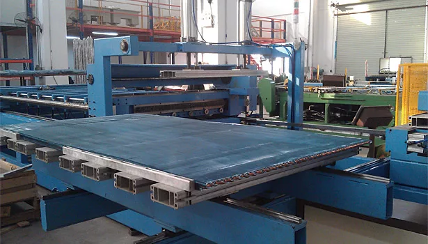
Technologies for manufacturing smaller diameter copper tubes are now available as well as the equipment for making coils from the smaller diameter copper tubes. These technologies have been developed and proven in the highly competitive manufacture of residential air conditioners. The same manufacturing technologies can be applied to a wide range of air conditioning and refrigeration products. The only limitation is the imagination of the designer.
Supply Chain
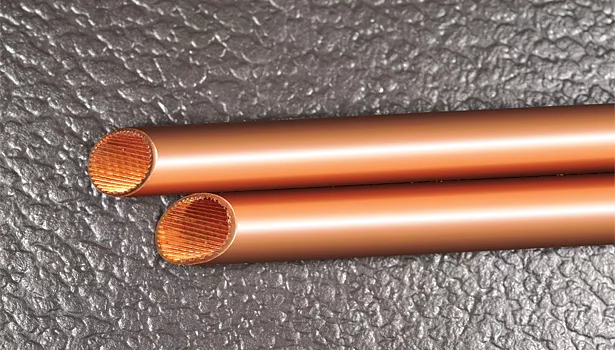
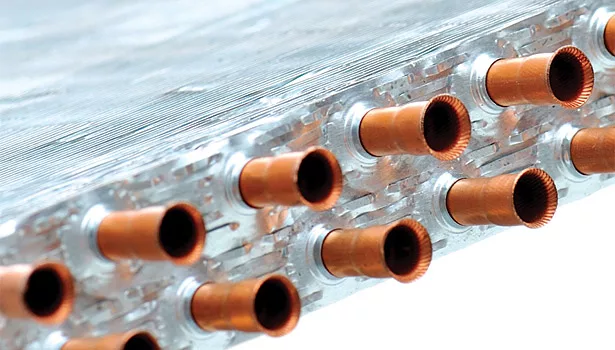
The International Copper Association uses the brand “MicroGroove” to promote the adoption of smaller diameter copper tubes with enhanced surfaces. Both of these features contribute to improved rates of heat transfer between the refrigerant and the tube walls, making it possible to use less material in smaller, lighter evaporators and condenser coils. ICA members supply many variants of microgroove technology, depending on application-specific needs and market focus. For example, the enhancements of the inside surface of the tubes vary widely from one tube manufacturer to another. Various patterns of inner grooves are used to further increase the local heat transfer coefficient for the transfer of heat between the refrigerant and the tube walls.
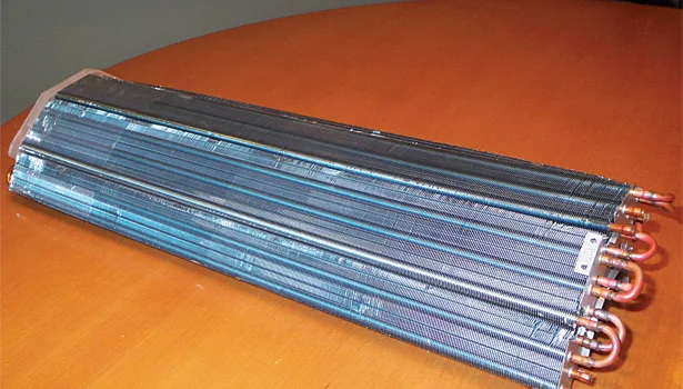
Round copper tubes offer several important advantages over brazed aluminum multichannel tubes. Using round copper tubes, heat transfer can be increased without the added costs and risks associated with aluminum brazing. In evaporator applications, moisture is more readily removed from the evaporator coils because there are no flat tubes between the fins but rather the fins surround round copper tubes, allowing for easy drainage.
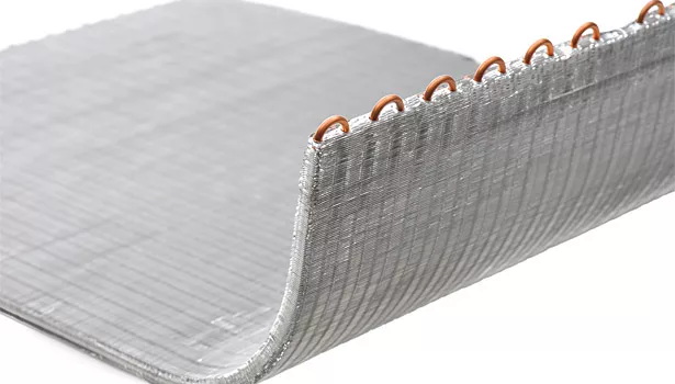
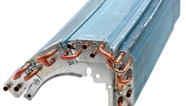
Durability is an issue. For most environments, copper tubes are preferred over aluminum tubes on the basis of durability and corrosion resistance. Copper is proven as a tube material in ACR applications. Costly coating processes, as often required for all aluminum heat exchangers, are not necessary. Finally, microgroove coils can offer smaller refrigerant volumes because the tube ends are connected by small U-joints rather than bulky headers associated with aluminum coils.
For more information, the interested reader is invited to contact ICA member companies directly. A list of MicroGroove contacts at member companies can be found on the supplier directory webpage at microgroove.net. In addition, technical papers and recorded webinars are available.
References
1. G.L. Ding, T Ren, Y.X. Zheng and Y.F. Gao, “Simulation-Based Design Method for Room Air Conditioner with Smaller Diameter Copper Tubes,” 23rd IIR International Congress of Refrigeration, Prague, Czech Republic, July 2011.
2. W. Wu, G.L. Ding, Y.X. Zheng, Y.F. Gao and J. Song, “Principle of Designing Fin-And-Tube Heat Exchanger with Smaller Diameter Tubes for Air Conditioner,” 14th International Refrigeration and Air Conditioning Conference, Purdue Conferences, West Lafayette, Indiana, July 2012.
Looking for a reprint of this article?
From high-res PDFs to custom plaques, order your copy today!


