Reduce Aerodynamic Noise
Learn more about the development of new methodologies for the reduction of aerodynamic noise in fans and blowers.
Aerodynamic noise is a rising source of concern for fans and blowers manufacturers across all industries, from domestic appliances and equipment to high speed cooling fans in IT and telecoms equipment.
In most applications concurrent requirements for high efficiency, high pressure and low noise are driving the fans and blowers developments to employ combinations of numerical simulations, such as Computational Fluid Dynamics (CFD), Computational Aero-Acoustics (CAA), and experimental measurements in anechoic chambers, but for many companies these high end resources are still prohibitive, particularly in regards to the associated product development costs to volumes of manufacturing of the final products.
Steady state CFD calculation can predict both aerodynamic efficiency and volume flow for given rotational speeds with relative good accuracy; however, most aero-acoustic analysis still requires unsteady computations which would run for days even on High Performance Computing (HPC) clusters. While these processes are the norm for the larger fans and blowers manufacturers, the length and costs of such analysis is prohibitive for the remaining majority of manufacturers when applied to daily product development activities; hence the requirements to actively look for more affordable tools and methodologies to drive product development to higher efficiencies and lower noise without incurring in exorbitant costs.
In essence concurrent aerodynamic and aero-acoustic optimizations are contrasting requirements, many fans and blowers are nowadays state-of-the-art designs and it is increasingly difficult to improve efficiency, pressure rise and noise.
One very important aspect of aerodynamic and aero-acoustic optimization is to understand the sources of noise and noise generation mechanisms for a variety of applications, a number of recent methods and their applications to fan design are reported below.
Design of high efficiency and low noise axial propeller fans:
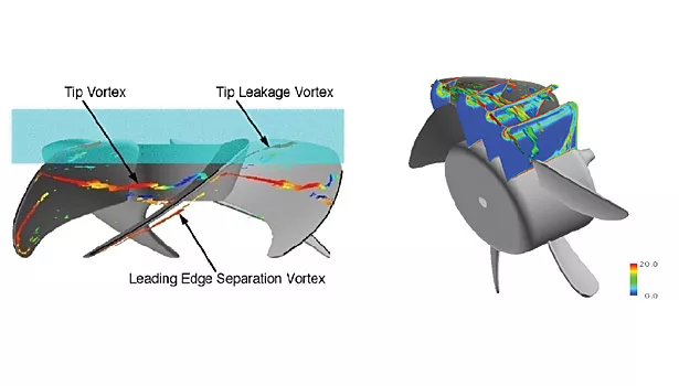
The Fan Noise Consortium, a large industrial effort with 16 industrial sponsors and four universities, sponsored by the Japanese Society of Mechanical Engineers (JSME), was aimed at identifying the main sources of noise in axial propeller fans for domestic appliances or cooling of desktops and laptops. These fans are generally characterized by relatively low speed, from a few hundred and up to 3,500 revolutions per minute, typical of these fans is the noise generated by the tip leakage flow from one blade hitting the following blade and generating noise. A typical example is illustrated in Figure 1.
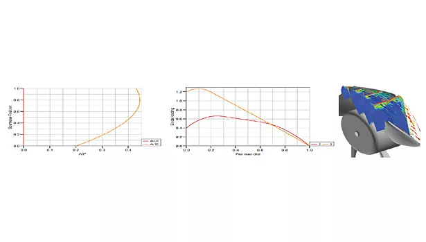
The consortium was aimed at identifying a set of design criteria for systematic design of high efficiency and low noise axial fan blades and included investigations of 22 different blade designs, 14 of which were manufactured and have been subject of detailed aerodynamic and aero-acoustic investigation in 3-D CFD and anechoic chamber. The work performed resulted in development of design guidelines for systematic design of high efficiency and low noise fans, the guidelines featured optimal spanwise distribution of work (rVt*) from hub to shroud and Streamwise Loading Distribution from leading edge to trailing edge.
Looking for quick answers on assembly and manufacturing topics? Try Ask ASM, our new smart AI search tool. Ask ASM
These guidelines are directly implementable for all designers in commercially available 3-D inverse design software, with this unique approach designers can directly control the aerodynamic and to an extent acoustic behavior of the blade subject to specific desired flow features which results in higher efficiency and lower noise blade design. A broadband noise model was also developed during the consortium for application to steady state CFD analysis and implemented in 3-D CFD codes.
High Speed IT & Telecoms Cooling Fans:
A second relevant application concerns IT servers and telecoms cooling units. These fans are characterized by requirements for higher pressure and rotational speeds are in the range of 10,000 to 20,000 rpm but lower noise is equally important. Sometimes these fans also feature contra-rotating elements. The guidelines previously reported are generally valid for higher speed fans as well. However, particular attention should be given to the tonal noise generation mechanisms which would dominate over broadband noise, in these higher speed rotors.
A tonal noise model was developed to be implemented in the 3-D inverse design code, the blade design code provides both the full three-dimensional geometry and the 3-D inviscid flow solution on the blade with fairly good agreement compared to full 3-D CFD calculations. The model uses a special Farassat’s formulation of the Ffowcs-Williams Hawkins method and relies on the calculated surface pressure distribution on the blade to output the noise spectrum data computed with respect to a specified observer position, this method is computationally very rapid, taking only a few seconds, and it is particularly well suited for design activities where the direction of design changes is preferred over the actual noise values.
Manual application of the methodologies described above can satisfy most of the design requirements in a short amount of time. A single design in 3-D inverse design tools takes only a few seconds to run providing both aerodynamic and tonal noise performance evaluation data; while a single passage, steady CFD calculation in 3-D CFD can be completed in less than 15 minutes on a mid-range workstation providing full 3-D CFD solution and broadband noise levels. However, how can both efficiency and aero-acoustic performance levels be pushed to the maximum extent?
Coupling of 3-D Inverse Design and Automatic Optimization:
One solution to satisfy all possible requirements is to couple blade design and analysis with automatic optimization tools, these tools automate the design and analysis activities and are driven by either genetic algorithms, for example NSGA-II Multi-Objective Genetic Algorithm (MOGA), or statistical methods and surrogate models, such as Response Surface Model or Kriging methods, or alternatively a combination of the two can be employed.
Each method provides its own advantages and disadvantages and it is not the intention of the author to enter into the details of the formulations, however the one key element common to all approaches is the quantity and quality of the design input parameters, or practically the 3-D blade geometrical definition in a parameterized way.
To illustrate the importance of the number of parameters two simple calculations are performed for a relatively simple optimization process based on DoE method, assuming that the 3-D blade shape is represented by 15 geometrical design parameters. DoE theory requires that for a Quadratic Response Surface Model (RSM) the minimum number of designs required is equal to (n+1)*(n+2)/2 where n is the number of design parameters. In this case, for n=15 we require at least 136 different designs to be analyzed.
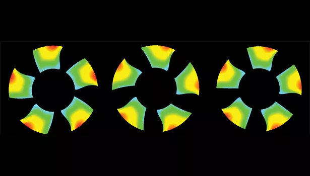
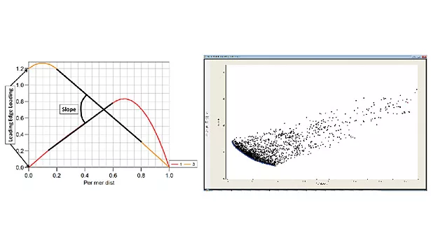
The blade parameterization implemented in 3-D inverse design is considerably different. Users specify the blade loading, or pressure jump across the blade, via a relatively simple parameterization as illustrated in Figure 4 (left). By controlling the leading edge loading at both hub and tip, the blade incidence is controlled, while the slope of the hub and tip loading curves controls the aerodynamic distribution, the code automatically scales the area underneath each curve to maintain and satisfy the input work coefficient, or essentially the blade pressure rise. With inclusion of the blade stacking, or wrap angle at hub or shroud at the trailing edge, a total of five design parameters can cover a relatively large design space as illustrated by the two fan designs in Figure 3 where only stacking was changed for values of -10, 0 and +10 wrap angle at the hub. Therefore following on the example above, with n=5 only 21 designs are needed.
Considering a product development environment where multiple operating points, five for the sake of this example, need to be analyzed, and considering 20min 3-D CFD analysis per point, the total time required for population of the DoE table is calculated as follows:
- Geometrical DoE: 5 operating points for 136 designs at 20min each = 13,600min or 9.4 days
- 3-D Inverse Design DoE: 5 operating points for 21 designs at 20min each = 2,100min or 1.45 days
A sample DoE optimization was performed for an axial fan case using the five parameters described above but instead of using the full 3-D CFD data, the aerodynamic and acoustic performances were evaluated directly from a 3-D inviscid solution on the blade surface, as described above.
Figure 4 presents the Pareto Front (blue line) of the above mentioned optimization routine where each design, represented by a dot, is evaluated for both tonal noise and profile loss, as an indicator of the blade efficiency. This unconstrained optimization shows that compared to the original design (pink lines) the optimization routine identified several design candidates featuring up to 13% reduction in profile loss, hence increase in efficiency, and up to 5% reduction in tonal noise. These designs are clearly situated at the extremities of the Pareto Front showing an inevitable tradeoff between efficiency and noise, although designers can comfortably select the design that best suits their requirements by selecting any point in-between these extremities.
The blade design, analysis and optimization methods highlighted are computationally affordable and aimed at improving designers’ capabilities to explore larger areas of the design space without longer product development times and costs; the solution is cost effective and affordable for the majority of fans and blowers manufacturers regardless of the intended product as all types of rotating and stationary blades for axial, mixed-flow and radial or centrifugal configurations can be designed within the same 3-D inverse design, 3-D CFD and automatic optimization process.
Looking for a reprint of this article?
From high-res PDFs to custom plaques, order your copy today!


