Press Fitting Railcar Wheelsets
The force-displacement curve can be influenced by part geometry, coefficient of friction, material strength and operating conditions.

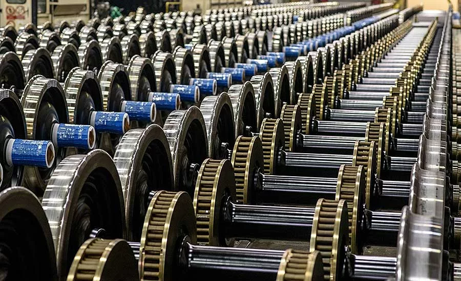
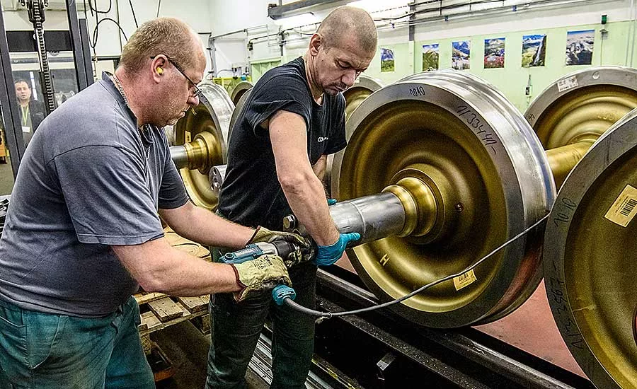
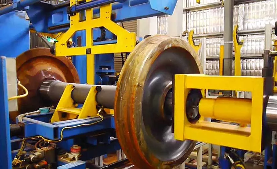
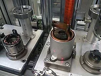
We tend to think of press fit assemblies as being relatively small. For example, a bushing for an automotive control arm assembly is typically less than 2 inches in diameter. But, much larger assemblies can also be accomplished with press fits, too. One example is railcar wheelsets. Railcar wheels are 36 inches in diameter and several inches wide. A wheelset—two wheels connected by an axle—can weigh more than 400 pounds.
Wheels can be press fit or shrink fit to axles. Also known as a force fit or interference fit, a press fit is an assembly in which one part is inserted tightly into a hole in another part. The assembly stays in place through friction and the force of the two parts pushing against each other. The process is reliable, simple, and does not require heating, cooling or soldering.
But, press fitting assemblies as large as railcar wheelsets takes care. Excessive interference can result in slip between the wheel and axle. Fretting wear can occur at the interface of the axle and wheel hub, and this can cause surface fatigue, adhesion, oxidation, exfoliation and scratching. Peak force limits and the force-displacement curve must be considered.
While there are international standards for wheelset assembly, including JIS E 4504, EN 13260 and ISO 100-5, they don’t provide much guidance on press fit assembly. And, few research projects have studied the force-displacement curve for wheelset assemblies. For example, one study investigated fretting wear in wheelset press fit joints. The researchers found that the adhesion phenomenon played a critical part in the initiation of fretting wear.
Lame’s equation can be used to determine contact pressures at the interface of the parts and to estimate the maximum holding torque capacity of a press fit. A major challenge of press fit assembly is to choose reasonable interference values that would ensure the safety of the assembled components. Too large an interference may damage the part being assembled, creating plastic deformation and ultimately, less torque resistance. To prevent slipping, the maximum holding torque capacity for the wheelset must be known. The magnitude of the press fit force depends on the geometry, friction coefficient, material properties and operating conditions.
With this in mind, we studied the effects of interference on press force. We used simulation to analyze the stress on the contact area between the wheel and the axle, and we discuss the stress-strain effects. We also determined the interferences needed for strong wheelset press fits. The force-displacement curve, maximum press force, and maximum holding torque were evaluated using finite element analysis.
Theoretical Analysis of Press fitting
In general, wheels and axles should meet geometric requirements as defined in EN 13261 for axles and EN 13262 for wheels. In press fitting, pressure is applied to the wheel hub to force it onto the axle, which is slightly larger in diameter. External pressure acts on the axle wheel seat, while internal pressure acts on the wheel hub. These two pressures are equal and opposite at the contact surface of the parts, assuming that the axle and wheel are made of the same material. Lame’s equation for contact pressure distribution in thick-walled cylinders was used for calculating the contact pressure between the two parts.
Looking for quick answers on assembly and manufacturing topics? Try Ask ASM, our new smart AI search tool. Ask ASM
EN 13260 specifies that the interference for press fitting should be 0.2 to 0.36 millimeter, which is based on the geometric tolerances of the axle wheel seats. The factors that mainly influence the maximum press force and characteristics of the force-displacement curve were the part geometry, coefficient of friction, material strength and operating conditions. During press fitting, the wheelset could be damaged by insufficient or excessive press force. Therefore, the force-displacement curve is important to determine that the assembly has not been damaged along the contact surfaces. If the force-displacement curve is not within the limits specified in the standard, the wheelset must be reassembled or rejected.
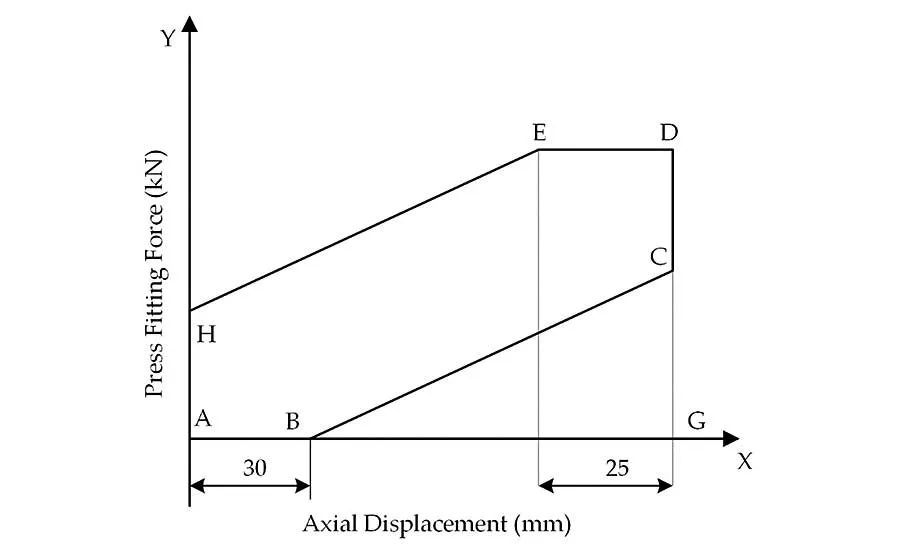
Figure 1 depicts a press fitting curve, showing force vs. displacement. The displacement is the movement of the wheel along the axle, since the axle is fixed to the clamping head of a machine. The standard requires the final fitting force to be between 0.85F and 1.45F. The axial force, F, in kilonewtons, is four times the mean diameter of the axle wheel seat. Axial displacement must be between 0.8d and 1.1d. The lines, AB, BC, HE and ED, define the boundaries of the force-displacement curve. Contact length is the X axis segment, AG. The points on the graph can be found by using the following equations: YH = 1.3ɸ; YC = 0.85F; and YD and YE = 1.45F. ɸ is the nominal diameter of the wheel seat in millimeters.
The press fitting force is related to many factors, including interference, the friction coefficient, and the elasticity of the parts. These factors can significantly change the press fitting force. The press fitting force to the wheel on the axle, Fp, can be calculated from the following equation: Fp = μ∫A PdA. In this equation, P is contact pressure in newtons per square millimeter; μ is the coefficient of friction, and A is the contact surface area in square millimeters. Thus, to obtain the press fit force, the contact pressure between the two assembly parts must be known.
Finite Element Analysis
Following the EN standard, EA1N and EA4T steel grades are widely used for railway axles. The materials of the wheel and axle were the same, homogeneous, and isotropic, with ideal elastic-plastic behavior.
To determine the press fitting force, a quarter 3D model of the wheel and axle assembly was made using Abaqus FEA software. During assembly, the wheel was moved onto the axle wheel seat by a custom assembly machine, so that interference between the assembly was eliminated for the outer diameter of the axle wheel seat, which was larger than the inner diameter. A static structure was analyzed, and the boundary conditions were used in the finite element analysis.
Taking advantage of the symmetric boundary conditions, the XY and XZ planes were constrained in the finite element model. The end of the axle was fixed, and an axial displacement of 180 millimeters was applied to the wheel hub towards the axle wheel seat. A contact pair was defined between the wheel- and axle-contacting surfaces. This analysis determined the press fitting force and stress distribution at the contact surface between the wheel and axle. A 2-millimeter mesh was used for the contact surface of the wheelset, and a 10-millimeter mesh was used for the other surfaces. The mesh type was a 20-node quadratic brick, reduced integration; 17,402 elements were used for the axle model, and 51,858 elements were used for the wheel model.
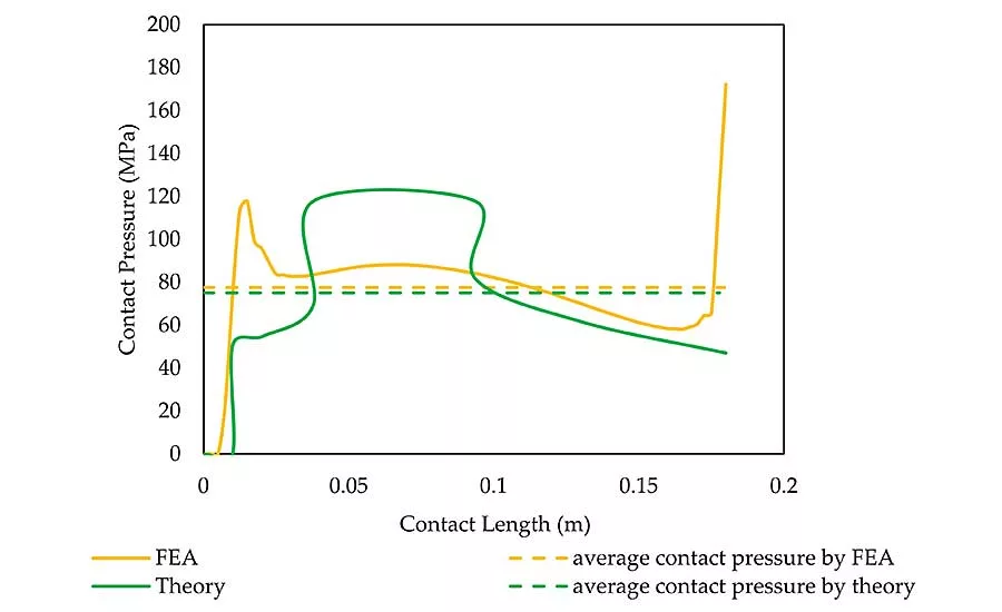
To verify the effectiveness of the numeric model, the finite element results were compared with the calculated theoretical results. The contact pressure between the wheel and axle wheel seat at different sections was determined, and the average contact pressure was calculated. The contact pressure of the axle reached its maximum at the end of the contact edge.
The finite element analyses led to higher average contact pressure than the theoretical model because the volume of the 3D model used in the finite element simulation was greater than that of the theoretical model. The finite element results were 3 percent greater than the theoretical ones. At the start of the wheelset assembly, the two parts did not contact each other because of the taper of the axle. Therefore, the press fitting force and contact pressure were zero until the end of the taper was reached, and then they suddenly increased.
The theory showed that the contact pressure was directly proportional to the outer radius or profile of the wheel and increased in the center of the contact region. The contact pressure of the axle increased sharply at the start of the contact and decreased towards the center of the contact length and maximum at the rear end of the edge.
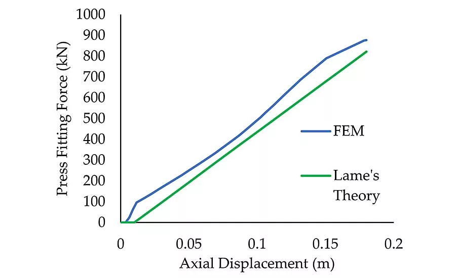
The maximum press fitting force at the end of the assembly was 877 kilonewtons from the finite element analysis and 822 kilonewtons from the theory, when the interference was 240 microns. The 7 percent difference between the results was considered acceptable.
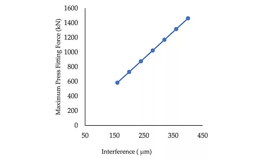
The interference was a significant factor that affected the press fitting curve. Simulations used interferences from 160 to 400 microns. The press fitting force increased, as expected, with the interference. The boundary of the press fitting curve was obtained from the EN 13260 standard.
The press fitting curves were used for monitoring the assembly and evaluating its quality. The curves for interferences of 160, 360, and 400 microns did not qualify because they were outside the EN 13260 boundary. One key conclusion from the simulations was that the interferences, specified by the EN standard, fell within the boundary. When the interference increased by 20 percent, the maximum press fitting force increased by 12 percent.
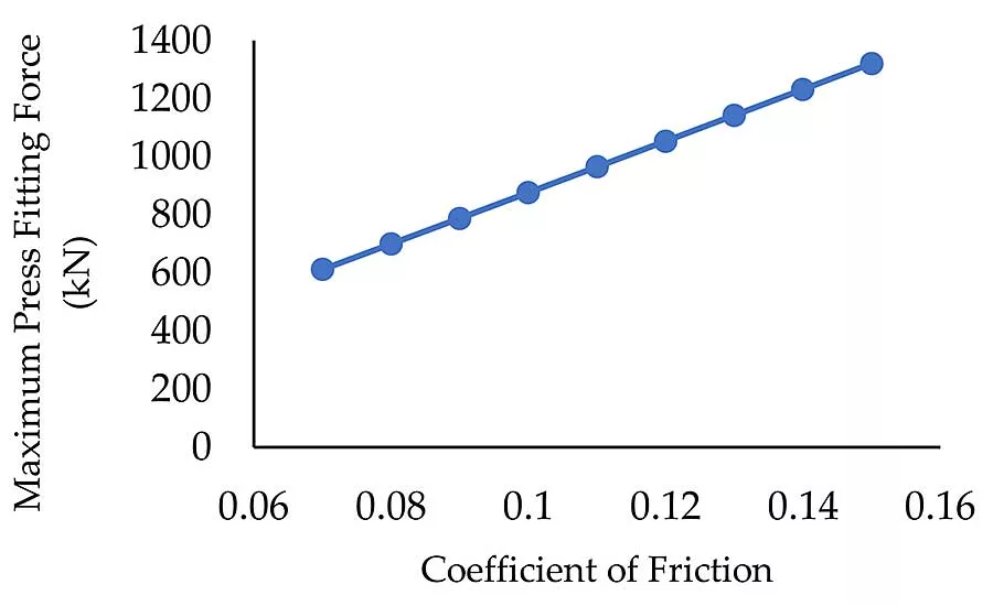
We observed that the friction coefficient affected the press fitting force during the assembly. Friction coefficients in the range 0.08 to 0.13 were the only ones acceptable. In general, the greater the friction coefficient, the greater the maximum press fitting force. Every 0.01 increment in the friction coefficient increased the maximum press fitting force by 14 percent.
Our simulations showed that the maximum von Mises stress took place at the wheel, in contact with the axle wheel seat taper area, in the first simulation time step. The stress was distributed symmetrically on both sides of the wheelset. The maximum stress occurred at the wheel hub bore after assembly. For the axle, the peak stress occurred at the start of the axle wheel seat at the end of the taper area. The maximum stress concentration was localized at the edge of the wheel hub because pressing the wheel to the axle induced critical stress due to the edge effect and abrupt transition in press fitting. It can be minimized by some geometric characteristics, friction coefficient, contact pressure and operation conditions. The simulations revealed that the interference value significantly affected the stress concentration.
To understand the effect of interference on deformation, note that for low values of interference, up to 360 microns, deformations in the assembly remained in the elastic range. However, for sufficiently large interferences, 380 microns or more, elastoplastic deformation occurred in the wheel. Elastic plastic deformation began at the edge of the wheel hub bore first.
Interference vs. Holding Torque
Railway wheelsets are generally running under many loading conditions, for example, vertical static forces of the vehicle; wheel and rail contact forces in longitudinal, vertical, and lateral directions; and inertial forces. In operation, the contact force, especially in the longitudinal direction, significantly increases as the train is accelerated or decelerated. This leads to a torsional moment on the wheelset, which may cause slippage at the wheel hub and axle seat.
The maximum holding torque capacity, T, is the torque required to prevent slip between the wheel and the axle, as it resists the motion of the wheelset at the contact surface. It is transmitted by frictional forces on the wheelset and can be evaluated using Lame’s equation. It was assumed that the contact pressure in the assembly was uniformly distributed. The radial interference was significant for the holding torque capacity, since it was related to the contact pressure and frictional force. The holding torque capacity of the wheelset, T, was thus a function of the friction coefficient, contact area and contact pressure: Fp = μ D/2 ∫A PdA.
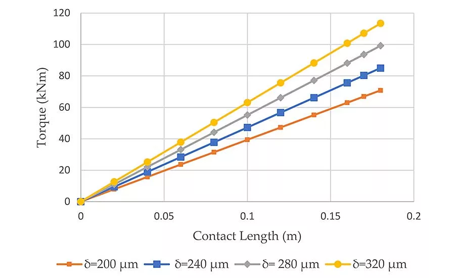
In this equation, μ is the static coefficient of friction; D is the axle diameter; P is the contact surface pressure; and A is the contact surface area. The holding torque capacity was related to the contact length of the press fit assembly. The maximum holding torque capacities were 71 kilonewton-meters for the interference of 200 microns, 85 kilonewton-meters for 240 microns, 99 kilonewton-meters for 280 microns, and 113 kilonewton-meters for 320 microns. Clearly, the holding torque capacity increased with the interference.
Finite element analysis was used to examine the effect of the interference on the holding torque capacity for the wheel and axle assembly. The geometry of the 3D models and materials properties were similar to those for the press fit analysis. During the holding torque analysis, surface-to-surface contact interaction was set between the wheel and axle interface with a contact interference fit option. A penalty frictional coefficient, 0.1, and hard contact were set as the contact properties.
It was necessary to define the reference points on the axle at both end-sides of the center point. To obtain more accurate results, a refined mesh was used at the contact area with a coarse mesh for the other areas. Torque loading was applied to the reference node at the end of the axle, and the outer surface of the wheel was fixed. The value of the applied torque was increased until rotation or slip occurred in the interface.
The torque capacity analysis simulated the wheel and axle assemblies to obtain the curves of the torque and rotational angle, which determined the maximum holding torque capacity for different interference values. The torque and rotational angle curves were needed to decide the torque required to resist the slip between the interference assemblies.
Within the elastic torque region, the shear stress in the axle varied linearly, and the axle showed only elastic deformation. When the torque increased to the plastic region, the axle rotated continuously with no further increase in the torque. The maximum elastic torque was equal to 75 percent of the maximum holding torque capacity at the fully plastic region. Therefore, it was evident that the maximum holding torque capacity or plastic torque, before slipping, was 75 kilonewton-meters at the twist angle 0.15 radian, and the maximum elastic torque was 56 kilonewton-meters at the twist angle 0.029 radian for the interference of 240 microns.
Elastic torque did not exceed the 75 percent of plastic torque for 240 microns. Other fit lengths were also less than 75 percent of the maximum holding torque capacity.
When the torque increased beyond the maximum holding torque capacity, the axle started slipping. Deviations between the estimated maximum holding torque capacities from the theory and finite element analyses all 15 percent or less.. Thus, the finite element results agreed with the theory.
Editor’s note: This article is a summary of a much longer research paper. To read the complete paper, click here.
Looking for a reprint of this article?
From high-res PDFs to custom plaques, order your copy today!