sponsored content
How To: Incorporate Robot Integration into your Indexing Application
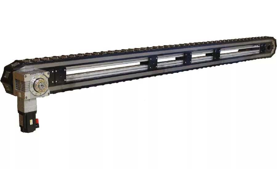
LFA precision indexing conveyors ready to accept robot auxiliary axis motors.
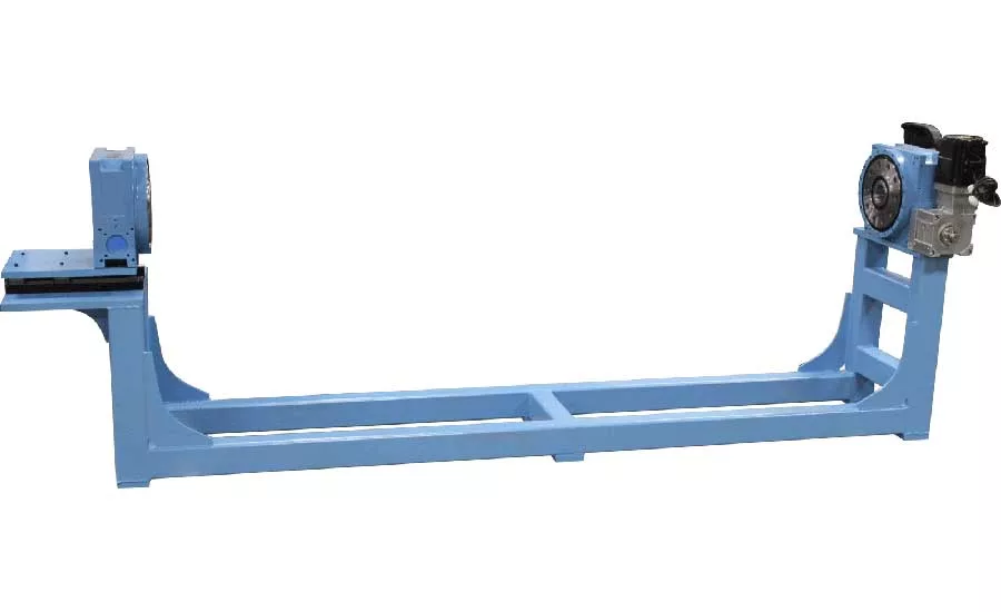
Precision Indexer mounted in trunnion configuration with Motoman auxiliary axis motor.

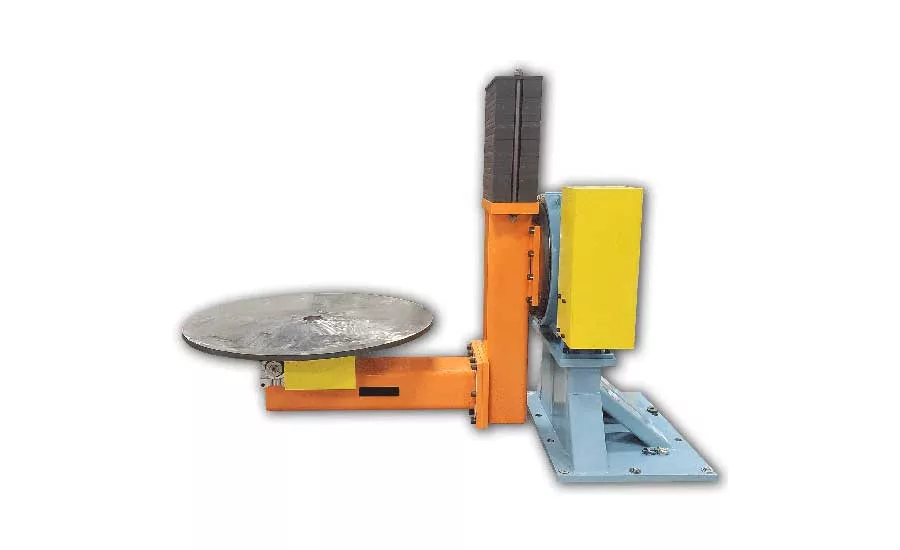
This sky hook device uses programmable indexers providing additional axis to a Fanuc welding robot.
When considering using an auxiliary axis motor for your rotary or linear axis application it is important to know a few important facts.
You will have to purchase the auxiliary axis motor or motors when you purchase your robot from the manufacturer or by providing a serial number of an existing robot. Your indexer manufacturer will recommend the size and required features that will work with the rotary indexer or linear indexing devices based on all the loading and application information that was provided.
Know that the size of indexer may have to increase in size over using a traditional servo motor or AC motor with encoder due to the limited movement profile capabilities of the robot software. Most robot software limits the movement profile to a trapezoidal move or triangular motion profile. Both require the acceleration and deceleration to be the same.
Avoid instantly applying brake on motor for all light screen violation and emergency stop conditions. A programmed deceleration for these occurrences must be implemented. There is additional software that is needed to be able program and to have an independent deceleration profile when these occurrences arise.
If you plan on operating your auxiliary axis indexer in one direction that you have software that can handle encoder count rollovers.
Make sure you are inputting the correct exact ratio into the drive. This can be done on some controllers by putting in the numerator/denominator or the exact calculated ratio. A common mistake is programmers looking at only the gear reducer provided on the indexer without adding the additional reduction in the indexer itself.
It is highly recommended to have a technician validate that an auxiliary axis system as been properly programmed to avoid any premature failures. This can be done on site or by video sharing applications. This is the #1 cause of any rotary or linear indexing device.
Looking for quick answers on assembly and manufacturing topics? Try Ask ASM, our new smart AI search tool. Ask ASM
If you have provided correct loading, implement the recommended movement profiles, avoid instantly applying the brake during light screen violations, your precision indexer should run flawless for many years.
The auxiliary axis rotary index tables that Motion Index Drives manufactures are extremely accurate and are a true zero backlash mechanism. The zero backlash is achieved from the cam technology that creates the transmission of the system. There are multiple cam followers arrayed toward the outer diameter of the rotating dial giving the system maximum strength for its overall size.
Like all rotary index table applications, the most important and starting factor in proper sizing is the mass moment of inertia. This will determine how fast you can rotate for a specific degree of rotation and in some occasions, how quickly can you stop the load. The mass moment of inertia will also be used to make sure the inertia mismatch is within an acceptable range for optimal control of the load. Because the Motion Index Drives auxiliar axis indexers are extremely rigid systems, we can have a mismatch of 10:1 of more and still have a very smooth, vibration free move without overtaxing the servo motor.
The most common robot manufactures offer auxiliary axis motors for their robots. An engineer will determine the maximum torque needed for the application and make a recommendation on what model auxiliary axis motor will be best suited. The sizing of the indexer can be affected if the customer requires a very quick stop during a light screen incursion event. If the stop time is 100 ms for instance it can create a very high force on the internal components compared to a 500 ms stop time. Most robot manufacturers offer special software packages for emergency stop occurrences which allow the programmer to adjust the deceleration times to soften the forces that will be realized during a light screen incursion or emergency stop. It is highly recommended to use the special software to be able to optimize the size of rotary index table for each application.
It is very important to know that when calculating the size of the indexer that will be required for an auxiliary axis application that the limitation for most robot manufacturers is the movement profile that can be used. In most cases when using an auxiliary axis motor the acceleration time has to match the deceleration time. It takes more torque to bring a load up to speed compared to bringing it to a stop, so when using an auxiliary axis motor that constraint alone can sometimes be the cause to increase the size of the indexer that will be best suited for that particular application. If movement profiles could be adjusted in aux axis software similar to servo motor applications, the acceleration can be prolonged and the deceleration can be shortened. In this situation the indexer can be optimized much better.
The possibilities don’t stop at the rotary index table. Motion Index Drives has a line of precision indexing conveyors that are offered as fully programmable linear indexing systems. Our precision indexing conveyors are used in automated processes that are layout in a linear fashion and required very high accuracy. They have an overall accuracy in X, Y, Z direction of +/- 0.06 mm. Traditionally these systems were operated with a fixed cam indexer. In recent years there has been more demand for flexibility without compromising the accuracy of the system. As with the rotary index tables more customer in the past few years have requested precision indexing conveyors that would be ready to accept robot servo motors.
Rotary index tables are commonly used in all types of automated processes, covering vast array of industries. Motion Index Drives manufactures and extensive line of rotary index tables that can be adapted to accommodate robot auxiliary axis motors ultimately providing an additional axis to the robot.
Ben Talan, President
Motion Index Drives
877-978-1830
Looking for a reprint of this article?
From high-res PDFs to custom plaques, order your copy today!


